// Simple WAV file player example
//
// Three types of output may be used, by configuring the code below.
//
//   1: Digital I2S - Normally used with the audio shield:
//         http://www.pjrc.com/store/teensy3_audio.html
//
//   2: Digital S/PDIF - Connect pin 22 to a S/PDIF transmitter
//         https://www.oshpark.com/shared_projects/KcDBKHta
//
//   3: Analog DAC - Connect the DAC pin to an amplified speaker
//         http://www.pjrc.com/teensy/gui/?info=AudioOutputAnalog
//
// To configure the output type, first uncomment one of the three
// output objects.  If not using the audio shield, comment out
// the sgtl5000_1 lines in setup(), so it does not wait forever
// trying to configure the SGTL5000 codec chip.
//
// The SD card may connect to different pins, depending on the
// hardware you are using.  Uncomment or configure the SD card
// pins to match your hardware.
//
// Data files to put on your SD card can be downloaded here:
//   http://www.pjrc.com/teensy/td_libs_AudioDataFiles.html
//
// This example code is in the public domain.

#include <Audio.h>
#include <Wire.h>
#include <SPI.h>
#include <SD.h>
#include <SerialFlash.h>

AudioPlaySdWav           playWav1;
// Use one of these 3 output types: Digital I2S, Digital S/PDIF, or Analog DAC
AudioOutputI2S           audioOutput;
//AudioOutputSPDIF       audioOutput;
//AudioOutputAnalog      audioOutput;
AudioConnection          patchCord1(playWav1, 0, audioOutput, 0);
AudioConnection          patchCord2(playWav1, 1, audioOutput, 1);
AudioControlSGTL5000     sgtl5000_1;

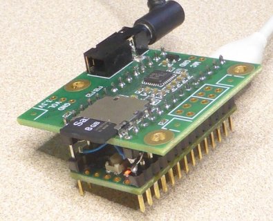
// Use these with the Teensy Audio Shield and Teesny 4.0  mdr20190823
#define SDCARD_CS_PIN    10
#define SDCARD_MOSI_PIN  11
#define SDCARD_SCK_PIN   13

// Use these with the Teensy Audio Shield
//#define SDCARD_CS_PIN    10
//#define SDCARD_MOSI_PIN  7
//#define SDCARD_SCK_PIN   14

// Use these with the Teensy 3.5 & 3.6 SD card
//#define SDCARD_CS_PIN    BUILTIN_SDCARD
//#define SDCARD_MOSI_PIN  11  // not actually used
//#define SDCARD_SCK_PIN   13  // not actually used

// Use these for the SD+Wiz820 or other adaptors
//#define SDCARD_CS_PIN    4
//#define SDCARD_MOSI_PIN  11
//#define SDCARD_SCK_PIN   13

void setup() {
  Serial.begin(9600);

  // Audio connections require memory to work.  For more
  // detailed information, see the MemoryAndCpuUsage example
  AudioMemory(8);

  // Comment these out if not using the audio adaptor board.
  // This may wait forever if the SDA & SCL pins lack
  // pullup resistors
  sgtl5000_1.enable();
  sgtl5000_1.volume(0.4);

  SPI.setMOSI(SDCARD_MOSI_PIN);
  SPI.setSCK(SDCARD_SCK_PIN);
  if (!(SD.begin(SDCARD_CS_PIN))) {
    // stop here, but print a message repetitively
    while (1) {
      Serial.println("Unable to access the SD card");
      delay(500);
    }
  }
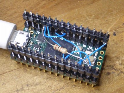
  //mdr20190828 IOMUXC stuff below was required to get SDcard to work and to attach to other boards.
  //from: https://forum.pjrc.com/threads/57167-Teensy-4-0-I2S-Support?p=213128&viewfull=1#post213128
  // defaults were all 0x10B0 which is keeper, Medium speed (100 Mhz), drive strength = R0/6 = 150/6 = 25 ohms (the second strongest drive strength available) // My changes were:
  IOMUXC_SW_PAD_CTL_PAD_GPIO_AD_B1_00 = 0xF808; // SCL, pullup at 22K, open drain enable, low speed, drive strength at R0 (150 ohm)
  IOMUXC_SW_PAD_CTL_PAD_GPIO_AD_B1_01 = 0xF808; // SDA
  IOMUXC_SW_PAD_CTL_PAD_GPIO_AD_B1_09 = 0x8; // MCLK, low speed, drive strength at R0 (150 ohm).
  IOMUXC_SW_PAD_CTL_PAD_GPIO_AD_B1_10 = 0x8; // BCLK
  IOMUXC_SW_PAD_CTL_PAD_GPIO_AD_B1_11 = 0x8; // LRCLK
  IOMUXC_SW_PAD_CTL_PAD_GPIO_B1_01 = 0x8; // OUT1A
  IOMUXC_SW_PAD_CTL_PAD_GPIO_B0_03 = 0x8; // SCK  mdr20190828 helped get to second read
  IOMUXC_SW_PAD_CTL_PAD_GPIO_B0_02 = 0x8; // SCK  mdr20190828 helped get to second read
}

void playFile(const char *filename)
{
  Serial.print("Playing file: ");
  Serial.println(filename);

  // Start playing the file.  This sketch continues to
  // run while the file plays.
  playWav1.play(filename);

  // A brief delay for the library read WAV info
  delay(5);

  // Simply wait for the file to finish playing.
  while (playWav1.isPlaying()) {
    // uncomment these lines if you audio shield
    // has the optional volume pot soldered
    //float vol = analogRead(15);
    //vol = vol / 1024;
    // sgtl5000_1.volume(vol);
  }
}


void loop() {
  playFile("SDTEST1.WAV");  // filenames are always uppercase 8.3 format
  delay(500);
  playFile("SDTEST2.WAV");
  delay(500);
  playFile("SDTEST3.WAV");
  delay(500);
  playFile("SDTEST4.WAV");
  delay(1500);
}


