You are using an out of date browser. It may not display this or other websites correctly.
You should upgrade or use an alternative browser.
You should upgrade or use an alternative browser.
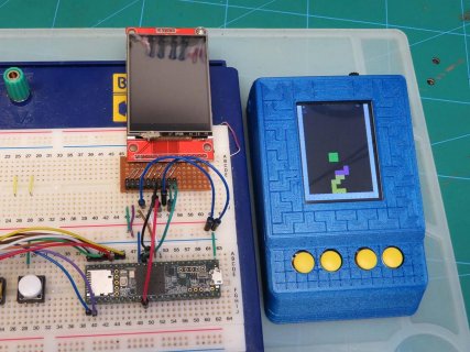
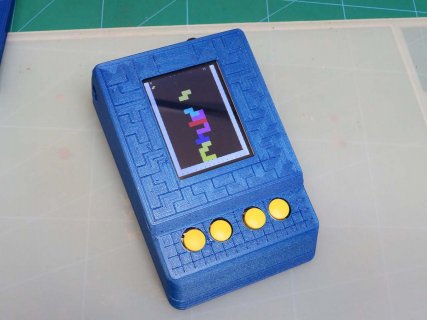
I am writing a simple Tetris Game using a Teensy 3.2 and a SPI based screen.
- Thread starter leejsmith
- Start date
- Status
- Not open for further replies.
defragster
Senior Member+
Always better when it works to good effect to enjoy it when done.
What display is in use? Looks like it could be an ILI9341 shown on the breadboard - there are variants of the good _t3 library that do DMA updates from a buffer in the background
What display is in use? Looks like it could be an ILI9341 shown on the breadboard - there are variants of the good _t3 library that do DMA updates from a buffer in the background
Always better when it works to good effect to enjoy it when done.
What display is in use? Looks like it could be an ILI9341 shown on the breadboard - there are variants of the good _t3 library that do DMA updates from a buffer in the background
Yes it's just a cheap ILI9341 type screen, Thanks I will take a look at those libs.
MichaelMeissner
Senior Member+
Yes it's just a cheap ILI9341 type screen, Thanks I will take a look at those libs.
In order to optimize the displays on Teensy 3.x systems, you will need to make sure both the CS pin and the D/C use the SPI0 fast pins. From the picture it looks like you are using pin 10 and pin 9 which are fast pins. The pins are:
- Pin 10 or pin 2 (but not both at the same time)
- Pin 9 or pin 6 (but not both at the same time)
- Pin 15/A1
- Pin 20/A6 or 23/A9 (but not both at the same time)
- Pin 21/A7 or 22/A8 (but not both at the same time)
- https://forum.pjrc.com/threads/33014-SPI-Chip-Selects-(Teensy-3-1-vs-3-2)?p=96072#post96072
Teensy 4.0 is different, and you pretty much have to use pin 10 on the first SPI bus for CS.
If you are sharing the SPI bus you want to use pull-up resistors in parallel between each of the CS and D/C pins and 3.3v. I imagine it also helps with high speed delays when there is only one thing on the bus. In my uncanny eyes setup (two displays), I've used 2.2K resistors. Using the pull-up resistors allowed me to bump up the SPI bus speed to run faster without screen corruption.
Obviously keep the wires as short as possible. After the initial setup and test, it generally is better if you solder the wires rather than use a breadboard. Obviously during the initial testing, having the flexibility to rearrange the wiring is really helpful, but at times, breadboards can make things less reliable at higher speeds (and if the device moves at all, wires can get unplugged).
In the SPI setup, you can specify the SPI bus speed, and some of the display libraries allow you to specify the speed. You can use this to tweak the display faster.
PJRC sells ILI9341 displays are tested (random displays you get from ebay, etc. may/may not have issues). The page also lists the main library and two alternative libraries:
I noticed your title says Teensy 3.2 but the picture you show is either a 3.5 or 3.6. It helps if you identify the right Teensy that you are using, in case there are specific differences. In terms of optimizing SPI devices, I believe the 3.2, 3.5, and 3.6 are the same. Note, the optimizations will not work on a Teensy LC, which does not have the DMA support for the optimizations, and as I said previously, the Teensy 4.0 is somewhat different in the details.
Last edited:
Thank you, I am using 9 and 10 and can see a big difference in speed when using the teensy optimized library from Paul Stoffregen when compared to the Adafruit one. Now I know about the DMA library I am keen to take a look at that on my teensy 3.6.
I developed using a the 3.6 running at the same speed as the 3.2, but it does have a 3.2 in the final version.
I developed using a the 3.6 running at the same speed as the 3.2, but it does have a 3.2 in the final version.
In order to optimize the displays on Teensy 3.x systems, you will need to make sure both the CS pin and the D/C use the SPI0 fast pins. From the picture it looks like you are using pin 10 and pin 9 which are fast pins. The pins are:
- Pin 10 or pin 2 (but not both at the same time)
- Pin 9 or pin 6 (but not both at the same time)
- Pin 15/A1
- Pin 20/A6 or 23/A9 (but not both at the same time)
- Pin 21/A7 or 22/A8 (but not both at the same time)
- https://forum.pjrc.com/threads/33014-SPI-Chip-Selects-(Teensy-3-1-vs-3-2)?p=96072#post96072
Teensy 4.0 is different, and you pretty much have to use pin 10 on the first SPI bus for CS.
If you are sharing the SPI bus you want to use pull-up resistors in parallel between each of the CS and D/C pins and 3.3v. I imagine it also helps with high speed delays when there is only one thing on the bus. In my uncanny eyes setup (two displays), I've used 2.2K resistors. Using the pull-up resistors allowed me to bump up the SPI bus speed to run faster without screen corruption.
Obviously keep the wires as short as possible.
In the SPI setup, you can specify the SPI bus speed, and some of the display libraries allow you to specify the speed. You can use this to tweak the display faster.
PJRC sells ILI9341 displays are tested (random displays you get from ebay, etc. may/may not have issues). The page also lists the main library and two alternative libraries:
blackketter
Well-known member
Thanks, Michael, that's very useful as I'm working on a T4 design with SPI.
You said:
What's the advice for having multiple devices on the SPI bus on a Teensy 4? Are there other pins that are recommended beyond pin 10?
You said:
Teensy 4.0 is different, and you pretty much have to use pin 10 on the first SPI bus for CS.
If you are sharing the SPI bus you want to use pull-up resistors in parallel between each of the CS and D/C pins and 3.3v.
What's the advice for having multiple devices on the SPI bus on a Teensy 4? Are there other pins that are recommended beyond pin 10?
MichaelMeissner
Senior Member+
If you need optimized SPI with DMA, such as running two displays, the posts I see from KurtE, mjs513, and defragster indicate that you should put each display on a separate SPI bus:What's the advice for having multiple devices on the SPI bus on a Teensy 4? Are there other pins that are recommended beyond pin 10?
- SPI0: SCLK = pin 13, MOSI = pin 11, MISO = pin 12, CS = pin 10;
- SPI1: SCLK = pin 27, MOSI = pin 26, MISO = pin 1, CS = pin 0; (MOSI/SCLK involve soldering to the 0.1"/2.54mm pads underneath the Teensy at the back); (and)
- SPI2: SCLK = pin 37, MOSI = pin 35, MISO = pin 34, CS = pin 36. (all pins involve soldering to the 1mm pads underneath the Teensy at the front).
In the Teensy 4.0, you don't seem to have multiple pins that can be used for DMA like you did in the 3.2, 3.5, and 3.6.
Note, I haven't personally delved into the mysteries of the data sheet (I do enough of that at work). This from seeing posts from them after I mentioned about the uncanny eyes program from Adafruit (two displays that make eyeballs that move around). They seem to have taken the ball and run with it, porting the new code Adafruit is using on their Monster M4SK board to support two 240x240 displays. Now part of the reasoning for using two SPI buses may be testing the cheap displays that don't have a CS pin, so for those displays you really do need two separate buses.
- Original 128x128 Teensy version: https://learn.adafruit.com/animated-electronic-eyes-using-teensy-3-1
- Adafruit Monster M4SK version: https://learn.adafruit.com/adafruit-monster-m4sk-eyes
- Thread on optimizing displays: https://forum.pjrc.com/threads/3875...r-version-of-ILI9341_t3-library-(ILI9341_t3n)
- The beta Teensy 4.0 thread: https://forum.pjrc.com/threads/54711-Teensy-4-0-First-Beta-Test
Hi all, I am now using the T3 lib and I setup to send the screen buffer and it was a lot slower to send the complete screen over how I had optimised my code to only send what was needed, but it's good to know how to use it.
On my teensy 3.6 test setup I started to write Space Invaders and I have made some good progress.
https://imgur.com/a/bKhSi5K
I started to look at adding audio and eventually found the Gameduino shield and was excited until I saw it's quite old and now the new version comes with a built in screen only. It was around £50 in the uk, so not something I can afford at the moment.
KrisKasprzak
Well-known member
great job on these games!
- Status
- Not open for further replies.


