You are using an out of date browser. It may not display this or other websites correctly.
You should upgrade or use an alternative browser.
You should upgrade or use an alternative browser.
I2C Slave on Teensy 4
- Thread starter RichardG
- Start date
- Status
- Not open for further replies.
alexandros
Well-known member
Uploading the wire multiple_slave_addresses example (by wire I mean not the raw, from the examples of your library), the Teensy seems to loose its serial port. What I mean is that after I upload this code the Arduino IDE can't see the Teensy any more and I only get /dev/ttyACM0 port (that's on Linux), where the Teensy is usually at /dev/ttyACM1. The same thing happened with both a Teensy 4.0 and a 4.1. Is there some way to remedy this?@AndyCap. I've merged that change.
Others might interested to know that latest version now allows the slave to listen to multiple addresses. This is handy if you want the Teensy to replace a bunch of different I2C devices.
alexandros
Well-known member
Uploading the wire multiple_slave_addresses example (by wire I mean not the raw, from the examples of your library), the Teensy seems to loose its serial port. What I mean is that after I upload this code the Arduino IDE can't see the Teensy any more and I only get /dev/ttyACM0 port (that's on Linux), where the Teensy is usually at /dev/ttyACM1. The same thing happened with both a Teensy 4.0 and a 4.1. Is there some way to remedy this?
Actually pressing the onboard button solved the port issue. But is there a known reason this is happening?
hojo
New member
I downloaded and got the library to work nicely. I'm attaching a Beaglebone Black as master and using the raw_slave_receiver example with successful results. On the bench, I'm using 15cm wires to connect between the two. There is sufficient pullup from either/both devices w/o any external for testing and I have also tested the 2.2k which works just fine. I'm not sure how I'm going to end up building this solution but I'm wondering how I test to determine which PU resisters to add in the final. The documents all read things like "long or short" runs but doesn't really quantify those lengths. Is this a job for an oscope and what would I look for? To that end, is it ok to pull up from the teensy with the external or should I be pulling up from the BBB or does it really matter? From what I can tell, the BBB requires external pullups in its default state and I'm happy to use external.
Also, and this is very important: thank you, Richard, for your library as it's exactly what I needed to get an i2c slave running on the T_4
Also, and this is very important: thank you, Richard, for your library as it's exactly what I needed to get an i2c slave running on the T_4
Hi hojo,
I'm really glad to hear that it's working for you.
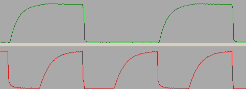
I2C sends signals by switching its lines between high and low. In effect it's sending a train of square waves down the wires. Any capacitance in the system rounds off the corners of the square waves like this:

Eventually, the waves become so rounded that they stop functioning like square waves. An oscilloscope will show you how square the waves are in your application.
Pull up resistors help to counteract the effect of capacitance by filling the capacitor more quickly.
The wires themselves act as weak capacitors. The capacitance is proportional to the length of the wires IIRC. This is why people use vague terms like "short" and "long" wires. A short wire is one where the capacitance is low enough to ignore. A long wire is one that requires pullups.
If your system works fine without pullups then leave them out. If you need pullups then fit the highest resistance that does the job. Lower resistances work fine too. They just consume more current. As far as I know, it doesn't matter where you put the resistors.
https://www.i2c-bus.org/i2c-primer/ discusses all of this in some detail. It's well written and has nice diagrams. The I2C specification https://www.nxp.com/docs/en/user-guide/UM10204.pdf contains hard numbers about allowed capacitance etc if you want them.
I hope this helps.
cheers,
Richard
I'm really glad to hear that it's working for you.
I2C sends signals by switching its lines between high and low. In effect it's sending a train of square waves down the wires. Any capacitance in the system rounds off the corners of the square waves like this:

Eventually, the waves become so rounded that they stop functioning like square waves. An oscilloscope will show you how square the waves are in your application.
Pull up resistors help to counteract the effect of capacitance by filling the capacitor more quickly.
The wires themselves act as weak capacitors. The capacitance is proportional to the length of the wires IIRC. This is why people use vague terms like "short" and "long" wires. A short wire is one where the capacitance is low enough to ignore. A long wire is one that requires pullups.
If your system works fine without pullups then leave them out. If you need pullups then fit the highest resistance that does the job. Lower resistances work fine too. They just consume more current. As far as I know, it doesn't matter where you put the resistors.
https://www.i2c-bus.org/i2c-primer/ discusses all of this in some detail. It's well written and has nice diagrams. The I2C specification https://www.nxp.com/docs/en/user-guide/UM10204.pdf contains hard numbers about allowed capacitance etc if you want them.
I hope this helps.
cheers,
Richard
- Status
- Not open for further replies.

