T4 FlexIO - Looking back at my T4 beta testing library FlexIO_t4

I got this working eventually.

Had to modify the following:
FLEXIO_SHIFTCTL_TIMPOL bit needs to be enabled to shift on negative edge
FLEXIO_TIMCFG_TSTOP time stop bit needs to be enabled

And then to read the data in the right order I read from SHIFTBUSBYS for a half word swap.
 
Please share that working code! As far as I know you are the first in this community to try parallel input with FlexIO.
 
We did quite a bit of playing with 4 bit parallel FlexIO for a cheap camera Sparkfun sells.

The camera itself turned out to be kind of underwhelming. FlexIO parallel was definitely working.
 
So, what is the status of the FlexIOSPI?

What is the maximum speed for FlexIOSPI?

What is the setup time for each transfer?

Thank you

(Referring to earlier posts in this thread, yes the SPI with ADC is running at 30MHz. Thank you again to everybody who helped. Since the datasheets says do-not-exceed for 30MHz, I have not tried running it faster.)
 
Please share that working code! As far as I know you are the first in this community to try parallel input with FlexIO.

Hey mate!
I've got a custom Teensy MM dev board with all 32 FlexIO2 pins exposed!
Was wondering if you could help me modify the DMA config to accept also 32 bit data array input and output 24 bits for RGB888 support? I'm quite rusty with my DMA knowledge these days :D
This means that there will be wasted 8 bits per shifter but im not really worried about that..
 
Sure, do you have it working with polling or interrupts already?
You will probably want to have each pixel stored in one 32 bit word in memory (24 bits of data and 8 bits of padding) to work most effectively.
 
Can you share a RGB888 version (non-DMA)? Not sure how the data is arranged in memory...

I don't have a working example yet, but it should be like this more or less:
Code:
FASTRUN void ILI948x_t4_mm::SglBeatWR_nPrm_32(uint32_t const cmd, const uint32_t *value, uint32_t const length)
{
 while(WR_DMATransferDone == false)
  {
    //Wait for any DMA transfers to complete
  }
    FlexIO_Config_SnglBeat();
    /* Assert CS, RS pins */
    CSLow();
    DCLow();
    //microSecondDelay();
    
    /* Write command index */
    p->SHIFTBUF[0] = cmd;

    /*Wait for transfer to be completed */
    while(0 == (p->TIMSTAT & (1 << 0)))
            {  
            }
    microSecondDelay();
    /* De-assert RS pin */
    DCHigh();
    microSecondDelay();

    if(length)
    {
      for(uint32_t i=0; i<length-1U; i++)
        {
            uint32_t argb888Value = *value++;
            uint32_t rgb888Value = argb888Value & 0x00FFFFFF;  // Discard the alpha channel
            uint32_t packedValue = ((rgb888Value >> 8) & 0xFF0000) | ((rgb888Value >> 5) & 0x00FF00) | ((rgb888Value >> 3) & 0x0000FF);
            while(0 == (p->SHIFTSTAT & (1U << 0)))
            {
            }
            p->SHIFTBUF[0] = packedValue;

        }

        /*Wait for transfer to be completed */
        while(0 == (p->TIMSTAT |= (1U << 0)))
        {
        }
    }
    microSecondDelay();
    CSHigh();
}
 
I would think it can be much simpler with 32 bit formatted data... If you just write p->SHIFTBUF[0] = argb888Value, does that work?
If you set FLEXIO_SHIFTCFG_PWIDTH(23) it should shift out 32 bits at a time, ignoring the upper 8 bits (alpha value).
 
Yeah its seems to work in polling mode by just feeding the shifter buffer with pointer to the frame buffer, no masking applied.

Now, how do I set up DMA to do that? I dont need to swap and bytes or half words around this time, so should be simpler
 
Try this code... I modified your library's FlexIO_Config_MultiBeat, MulBeatWR_nPrm_DMA, and flexDma_Callback. You will need to update the single beat configuration for 24 bit PWIDTH and other stuff. In the header, you need to change MulBeatDataRemain from type uint16_t* to uint32_t*. I don't have a way to test this currently but hopefully it works.

Code:
FASTRUN void ILI948x_t4_mm::FlexIO_Config_MultiBeat() {
  uint32_t i;
  uint8_t MulBeatWR_BeatQty = SHIFTNUM * sizeof(uint32_t) / sizeof(uint32_t);  //Number of beats = number of shifters * beats per shifter
  /* Disable and reset FlexIO */
  p->CTRL &= ~FLEXIO_CTRL_FLEXEN;
  p->CTRL |= FLEXIO_CTRL_SWRST;
  p->CTRL &= ~FLEXIO_CTRL_SWRST;

  gpioWrite();

  for (i = 0; i <= SHIFTNUM - 1; i++) {
    p->SHIFTCFG[i] =
      FLEXIO_SHIFTCFG_INSRC * (1U)   /* Shifter input from next shifter's output */
      | FLEXIO_SHIFTCFG_SSTOP(0U)    /* Shifter stop bit disabled */
      | FLEXIO_SHIFTCFG_SSTART(0U)   /* Shifter start bit disabled and loading data on enabled */
      | FLEXIO_SHIFTCFG_PWIDTH(23U); /* 32 bit shift, with 24 output pins (upper 8 bits are discarded) */
  }

  p->SHIFTCTL[0] =
    FLEXIO_SHIFTCTL_TIMSEL(0)       /* Shifter's assigned timer index */
    | FLEXIO_SHIFTCTL_TIMPOL * (0U) /* Shift on posedge of shift clock */
    | FLEXIO_SHIFTCTL_PINCFG(3U)    /* Shifter's pin configured as output */
    | FLEXIO_SHIFTCTL_PINSEL(4)     /* Shifter's pin start index */
    | FLEXIO_SHIFTCTL_PINPOL * (0U) /* Shifter's pin active high */
    | FLEXIO_SHIFTCTL_SMOD(2U);     /* shifter mode transmit */

  for (i = 1; i <= SHIFTNUM - 1; i++) {
    p->SHIFTCTL[i] =
      FLEXIO_SHIFTCTL_TIMSEL(0)       /* Shifter's assigned timer index */
      | FLEXIO_SHIFTCTL_TIMPOL * (0U) /* Shift on posedge of shift clock */
      | FLEXIO_SHIFTCTL_PINCFG(0U)    /* Shifter's pin configured as output disabled */
      | FLEXIO_SHIFTCTL_PINSEL(4)     /* Shifter's pin start index */
      | FLEXIO_SHIFTCTL_PINPOL * (0U) /* Shifter's pin active high */
      | FLEXIO_SHIFTCTL_SMOD(2U);     /* shifter mode transmit */
  }

  /* Configure the timer for shift clock */
  p->TIMCMP[0] =
    ((MulBeatWR_BeatQty * 2U - 1) << 8) /* TIMCMP[15:8] = number of beats x 2 – 1 */
    | (_buad_div / 2U - 1U);            /* TIMCMP[7:0] = shift clock divide ratio / 2 - 1 */

  p->TIMCFG[0] = FLEXIO_TIMCFG_TIMOUT(0U)       /* Timer output logic one when enabled and not affected by reset */
                 | FLEXIO_TIMCFG_TIMDEC(0U)     /* Timer decrement on FlexIO clock, shift clock equals timer output */
                 | FLEXIO_TIMCFG_TIMRST(0U)     /* Timer never reset */
                 | FLEXIO_TIMCFG_TIMDIS(2U)     /* Timer disabled on timer compare */
                 | FLEXIO_TIMCFG_TIMENA(2U)     /* Timer enabled on trigger high */
                 | FLEXIO_TIMCFG_TSTOP(0U)      /* Timer stop bit disabled */
                 | FLEXIO_TIMCFG_TSTART * (0U); /* Timer start bit disabled */


  p->TIMCTL[0] =
    FLEXIO_TIMCTL_TRGSEL(((SHIFTNUM - 1) << 2) | 1U) /* Timer trigger selected as highest shifter's status flag */
    | FLEXIO_TIMCTL_TRGPOL * (1U)                    /* Timer trigger polarity as active low */
    | FLEXIO_TIMCTL_TRGSRC * (1U)                    /* Timer trigger source as internal */
    | FLEXIO_TIMCTL_PINCFG(3U)                       /* Timer' pin configured as output */
    | FLEXIO_TIMCTL_PINSEL(0)                        /* Timer' pin index: WR pin */
    | FLEXIO_TIMCTL_PINPOL * (1U)                    /* Timer' pin active low */
    | FLEXIO_TIMCTL_TIMOD(1U);                       /* Timer mode 8-bit baud counter */

  /*
  Serial.printf("CCM_CDCDR: %x\n", CCM_CDCDR);
  Serial.printf("VERID:%x PARAM:%x CTRL:%x PIN: %x\n", IMXRT_FLEXIO2_S.VERID, IMXRT_FLEXIO2_S.PARAM, IMXRT_FLEXIO2_S.CTRL, IMXRT_FLEXIO2_S.PIN);
  Serial.printf("SHIFTSTAT:%x SHIFTERR=%x TIMSTAT=%x\n", IMXRT_FLEXIO2_S.SHIFTSTAT, IMXRT_FLEXIO2_S.SHIFTERR, IMXRT_FLEXIO2_S.TIMSTAT);
  Serial.printf("SHIFTSIEN:%x SHIFTEIEN=%x TIMIEN=%x\n", IMXRT_FLEXIO2_S.SHIFTSIEN, IMXRT_FLEXIO2_S.SHIFTEIEN, IMXRT_FLEXIO2_S.TIMIEN);
  Serial.printf("SHIFTSDEN:%x SHIFTSTATE=%x\n", IMXRT_FLEXIO2_S.SHIFTSDEN, IMXRT_FLEXIO2_S.SHIFTSTATE);
  for(int i=0; i<SHIFTNUM; i++){
    Serial.printf("SHIFTCTL[%d]:%x \n", i, IMXRT_FLEXIO2_S.SHIFTCTL[i]);
    } 

  for(int i=0; i<SHIFTNUM; i++){
    Serial.printf("SHIFTCFG[%d]:%x \n", i, IMXRT_FLEXIO2_S.SHIFTCFG[i]);
    }   
  
  Serial.printf("TIMCTL:%x %x %x %x\n", IMXRT_FLEXIO2_S.TIMCTL[0], IMXRT_FLEXIO2_S.TIMCTL[1], IMXRT_FLEXIO2_S.TIMCTL[2], IMXRT_FLEXIO2_S.TIMCTL[3]);
  Serial.printf("TIMCFG:%x %x %x %x\n", IMXRT_FLEXIO2_S.TIMCFG[0], IMXRT_FLEXIO2_S.TIMCFG[1], IMXRT_FLEXIO2_S.TIMCFG[2], IMXRT_FLEXIO2_S.TIMCFG[3]);
  Serial.printf("TIMCMP:%x %x %x %x\n", IMXRT_FLEXIO2_S.TIMCMP[0], IMXRT_FLEXIO2_S.TIMCMP[1], IMXRT_FLEXIO2_S.TIMCMP[2], IMXRT_FLEXIO2_S.TIMCMP[3]);
  */
  /* Enable FlexIO */
  p->CTRL |= FLEXIO_CTRL_FLEXEN;
  p->SHIFTSDEN |= 1U << (SHIFTER_DMA_REQUEST);  // enable DMA trigger when shifter status flag is set on shifter SHIFTER_DMA_REQUEST
}

Code:
FASTRUN void ILI948x_t4_mm::MulBeatWR_nPrm_DMA(uint32_t const cmd, const void *value, uint32_t const length) {
  while (WR_DMATransferDone == false) {
    //Wait for any DMA transfers to complete
  }
  const uint32_t BeatsPerMinLoop = SHIFTNUM * sizeof(uint32_t) / sizeof(uint32_t);  // Number of shifters * number of beats per shifter
  const uint32_t BeatsPerPixel = 1;                                                 // each pixel is written in a single beat
  uint32_t majorLoopCount, minorLoopBytes;
  uint32_t destinationModulo = 31 - (__builtin_clz(SHIFTNUM * sizeof(uint32_t)));  // defines address range for circular DMA destination buffer

  FlexIO_Config_SnglBeat();
  CSLow();
  DCLow();

  /* Write command index */
  p->SHIFTBUF[0] = cmd;

  /*Wait for transfer to be completed */
  while (0 == (p->TIMSTAT & (1 << 0))) {
  }
  microSecondDelay();
  /* De-assert RS pin */
  DCHigh();
  microSecondDelay();

  if (length < SHIFTNUM) {
    //Serial.println ("In DMA but to Short to multibeat");
    const uint32_t *newValue = (uint32_t *)value;
    for (uint32_t i = 0; i < length; i++) {
      while (0 == (p->SHIFTSTAT & (1U << 0))) {
      }
      p->SHIFTBUF[0] = *newValue++;
    }
    //Wait for transfer to be completed
    while (0 == (p->TIMSTAT & (1U << 0))) {
    }

    microSecondDelay();
    CSHigh();

  } else {

    FlexIO_Config_MultiBeat();

    MulBeatCountRemain = length % (BeatsPerMinLoop / BeatsPerPixel);          // number of pixels remaining after DMA transfer completes
    MulBeatDataRemain = (uint32_t *)value + ((length - MulBeatCountRemain));  // pointer to the next unused byte (overflow if MulBeatCountRemain = 0)
    TotalSize = (length - MulBeatCountRemain) * sizeof(uint32_t);             /* DMA transfer size in bytes */
    minorLoopBytes = SHIFTNUM * sizeof(uint32_t);
    majorLoopCount = TotalSize / minorLoopBytes;

    /* Configure FlexIO with multi-beat write configuration */
    flexDma.begin();

    /* Setup DMA transfer to FlexIO shifter buffers
     * Each minor loop fills SHIFTBUF[0] through SHIFTBUF[SHIFTNUM-1] with 32-bit data.
     * Data is copied using 32 bit writes. */

    int destinationAddressOffset, destinationAddressLastOffset, sourceAddressOffset, sourceAddressLastOffset;
    volatile void *destinationAddress, *sourceAddress;

    sourceAddress = (volatile uint32_t *)value;
    sourceAddressOffset = sizeof(uint32_t);
    sourceAddressLastOffset = 0;
    destinationAddress = &(p->SHIFTBUF[0]);
    destinationAddressOffset = sizeof(uint32_t);
    destinationAddressLastOffset = 0;

    flexDma.TCD->SADDR = sourceAddress;
    flexDma.TCD->SOFF = sourceAddressOffset;
    flexDma.TCD->SLAST = sourceAddressLastOffset;
    flexDma.TCD->DADDR = destinationAddress;
    flexDma.TCD->DOFF = destinationAddressOffset;
    flexDma.TCD->DLASTSGA = destinationAddressLastOffset;
    flexDma.TCD->ATTR =
      DMA_TCD_ATTR_SMOD(0U)
      | DMA_TCD_ATTR_SSIZE(DMA_TCD_ATTR_SIZE_32BIT)  // 32bit reads
      | DMA_TCD_ATTR_DMOD(destinationModulo)
      | DMA_TCD_ATTR_DSIZE(DMA_TCD_ATTR_SIZE_32BIT);  // 32bit writes
    flexDma.TCD->NBYTES_MLNO = minorLoopBytes;
    flexDma.TCD->CITER = majorLoopCount;  // Current major iteration count
    flexDma.TCD->BITER = majorLoopCount;  // Starting major iteration count

    flexDma.triggerAtHardwareEvent(hw->shifters_dma_channel[SHIFTER_DMA_REQUEST]);
    flexDma.disableOnCompletion();
    flexDma.interruptAtCompletion();
    flexDma.clearComplete();

    //Serial.println("Dma setup done");

    /* Start data transfer by using DMA */
    WR_DMATransferDone = false;
    flexDma.attachInterrupt(dmaISR);
    flexDma.enable();
    //Serial.println("Starting transfer");
    dmaCallback = this;
  }
}

Code:
FASTRUN void ILI948x_t4_mm::flexDma_Callback() {
  //Serial.printf("DMA callback start triggred \n");

  /* the interrupt is called when the final DMA transfer completes writing to the shifter buffers, which would generally happen while
    data is still in the process of being shifted out from the second-to-last major iteration. In this state, all the status flags are cleared.
    when the second-to-last major iteration is fully shifted out, the final data is transfered from the buffers into the shifters which sets all the status flags.
    if you have only one major iteration, the status flags will be immediately set before the interrupt is called, so the while loop will be skipped. */
  while (0 == (p->SHIFTSTAT & (1U << (SHIFTNUM - 1)))) {
  }

  /* Wait the last multi-beat transfer to be completed. Clear the timer flag
    before the completing of the last beat. */
  p->TIMSTAT |= (1U << 0U);

  /* Wait timer flag to be set to ensure the completing of the last beat. */
  // 2023-06-24 uncommented this loop because I don't think it risks an infinite loop and should waste less time than the software delay.
  while (0 == (p->TIMSTAT & (1U << 0U))) {
  }

  //  delayMicroseconds(200);

  if (MulBeatCountRemain) {
    //Serial.printf("MulBeatCountRemain in DMA callback: %d, MulBeatDataRemain %x \n", MulBeatCountRemain,MulBeatDataRemain);

    /* Configure FlexIO with 1-beat write configuration */
    FlexIO_Config_SnglBeat();

    //Serial.printf("Starting single beat completion: %d \n", MulBeatCountRemain);

    /* Use polling method for data transfer */
    for (uint32_t i = 0; i < (MulBeatCountRemain); i++) {
      while (0 == (p->SHIFTSTAT & (1U << 0))) {
      }
      p->SHIFTBUF[0] = *MulBeatDataRemain++;
    }
    p->TIMSTAT |= (1U << 0);

    /* Wait for transfer to be completed */
    while (0 == (p->TIMSTAT |= (1U << 0))) {
    }
    //Serial.println("Finished single beat completion");
  }
  microSecondDelay();
  CSHigh();

  WR_DMATransferDone = true;
  //    flexDma.disable(); // not necessary because flexDma is already configured to disable on completion
  if (isCB) {
    //Serial.printf("custom callback triggred \n");
    _onCompleteCB();
  }
  //Serial.printf("DMA callback end triggred \n");
}
 
Try this code... I modified your library's FlexIO_Config_MultiBeat, MulBeatWR_nPrm_DMA, and flexDma_Callback. You will need to update the single beat configuration for 24 bit PWIDTH and other stuff. In the header, you need to change MulBeatDataRemain from type uint16_t* to uint32_t*. I don't have a way to test this currently but hopefully it works.

What a legend! Thanks again Eric!
I'll implement and test it this week

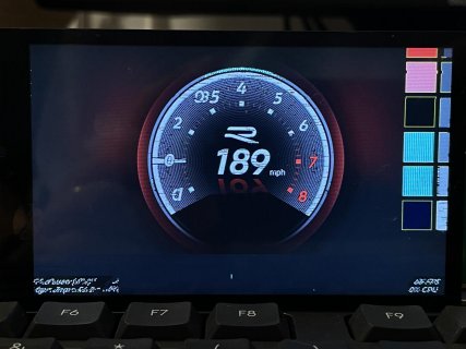
I've been playing with Polling for now, and while I am facing some issue with artifacts on the screen and some colors being off, 24 bit color does look so much better!
 
It seems to be working in a nutshell..
But something is way off with this display or my code haha

IMG_1938.jpg

I gotta say though, it looks real good at 24 bit color depth and it's fast with the 24 bit bus!
 
Check you have all the parallel wires connected to the right pins... Or maybe try replacing SHIFTBUF WITH SHIFTBUFBYS, SHIFTBUFBBS, or SHIFTBUFBIS and see if that looks better.
 
I think that there might be interference with the wires. As I have tested all the pins and they seem to work fine.
It could also be missing some register settings in the display. I'll investigate.

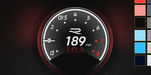
For reference, here is the original image that is being displayed:
golfgti2022.png
 
Back
Top