Vadim Lopatin
Member
Hello!
I'm working on my hobby digital theremin project.
Theremin is musical instrument controlled by distance between player's hand and antennas.
In theremin, there are two antennas - one for pitch control and second for volume control. Pitch antenna (right) is usually straight conducting rod, and volume antenna is loop-shaped conducting rod oriented horizontally.
Classic theremins are analog - pitch oscillator frequency is being converted to audible range using heterodyning, and volume antenna cirquit produces volume control voltage to shape pitch signal using VCA.
Digital theremins are actually digital synthesizers controlled by theremin sensors.
This project is started to provide digital theremin design, which is
Challenges: sensors
When hand approaches antenna, its capacicance increases. Total range of capacitance change due to hand movement is about 1.5pF
Antenna self-capacitance is near 7-8pF. To capture hand movements it's necessary to measure antenna capacitance with very high precision.
C of antenna non-linearly depends on hand range. Each 10cm of additional distance reduce C introduced by hand by ~3.5 times. Required distance measurement precision is about 1mm.
It's easy measure C for short distances - when it changes by 0.1..0.01pF. Even RC based sensor might work on 10cm distance.
But the bigger is distance, the finer resolution of C sensor is needed. Averaging of sensor output could increase precision, but introduces latency.
Good theremin should have low latency (less than 1ms). As bad example of digital theremin sensor design you can try Moog Theremini (latency is 0.1..0.5 seconds!!!)
High precision measurement of C requires LC tank with high Q. L should be big enough (0.5mH..10mH), C should be small (C = C_ant + C_hand + C_internal) to keep good sensitivity.
We can either measure of LC oscillator frequency (1) or measure amplitude or phase shift of reference signal passed through LC (2).
(for reference signal frequency close to LC resonance phase shift is PI/2 and amplitude is max; phase shift is easier to track than amplitude change).
For (1) we have to be able measure frequency with very high precision. LC oscillator frequency (in range 0.2MHz..3Mhz varying by 1..5% depending on hand distance) can be either measured directly (requires very high resolution of measurement timer) or converted to lower frequency higher relative change signal using some heterodyning technique.
In digital theremins (like Open.Theremin) there is often used D-trigger based heterodyne which converts oscillator frequency to easy measurable range. But it has aliasing issues and not enough good performance.
(I've tried this approach in Teensy 3.6 based implementation - it's not precise enough).
For (2) we can convert phase shift to PWM using XOR between LC input and output, convert to voltage using lowpass filter, then measure using ADC.
I've experimented a lot with FPGA based design, where main purpose of FPGA was to implement high precision frequency measure - until I visited pjrc site and found that there is Teensy 4.0 available.
Now I switched to development of digital theremin design based on Teensy 4.0 and Teensy Audio Adaptor (revD).
600/800MHz is more than enough for virtually
Although Teensy 4.0 timer performance is higher than one in Teensy 3.6 (150MHz or even 200MHz overclocked vs 60MHz), it's still not enough for direct measure of oscillator frequency.
Possible solution could be to use external IC like TDC7200, but I'm trying to find some easy to build solution, to minimize soldering while providing high sensitivity and low latency.
Main challenge is design of Pitch antenna sensor able to provide enough bits of distance value for hand distances 80..100cm from antenna.
Phase shift based approach (2) is possible, but requires external ADC (24 bits looks enough according to simulation).
LTSpice model:

LTSpice simulation results - output voltage depending on C_hand with 0.1pF steps:

I hope, this approach can be used for volume antenna where far distances are not required (30..40cm max are usual) - even when measured by Teensy 4.0 internal ADC.
Pitch sensor.
How do we implement sensitive sensor for pitch antenna?
We can go closer to analog theremins.
What if we pass LC oscillator output (F_osc) through heterodyne (mixing with F_ref) to get output signal with frequency F_ref-F_osc?
Oscillator will provide clean sine output. Heterodyne can be built based on analog switch - if F_osc is sampled at F_ref rate and passed through LP filter, output will be clean sine of frequency F_ref-F_osc.
We already have higher precision ADC than one in Teensy 4.0 - it's SGTL5000 from audio board which can provide 16-24 bits once per sample - if Line In of Audio Adaptor is used as ACD.
We only need to make sure that frequency and amplitude of heterodyne output matches Line In capabilities.
How do we measure frequency of heterodyne output? It may vary in amplitude (there is signal damping when hand is close to antenna). Of course, we could detect zero crossings and use interpolation to determine exact time of crossing.
But isn't it possible to have measured value for each sample, not only when signal crosses zero? Tricks with asin() and autocalibration of amplitude, but there is a better way.
Let's use two heterodyne channels, with PI/2 shift between them (use both left and right channels of Line In). In this case we can simple use tan2() on each sample to get phase value signal not dependent on amplitude changes.
We need two reference frequency signals, phase shifted by PI/2, with small duty cycle (0.05..0.2). To achieve this, we can use FlexPWM.
Divider value K for PWM should be divisible by 4 if we need exact PI/2 phase shift. Difference between F_BUS/K and F_BUS/(K+4) should be small enough (e.g. <5KHz) to allow calibration to fit signal in LineIn frequency range.
So, oscillator frequency needs to be < 500KHz.
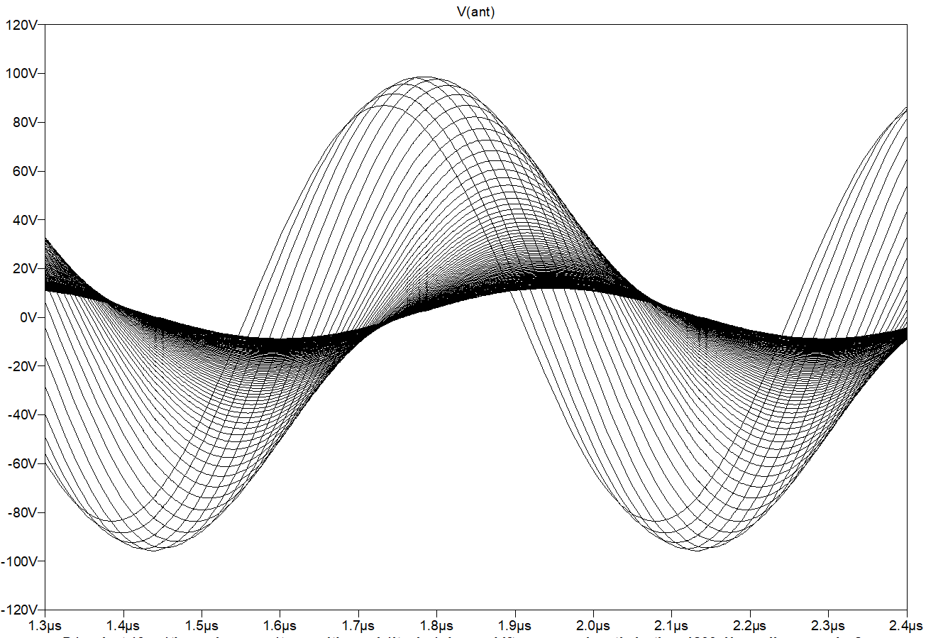
LTSpice model:

Simulation results - quadrant output to be passed to Audio Adaptor Line In:

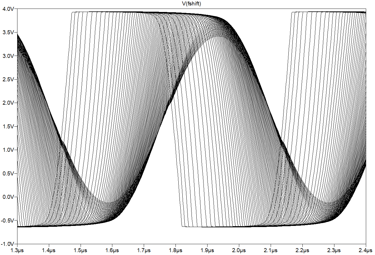
Reference frequency signals and oscillator output:

Sensor signal, after calibration, will provide LineIn frequency change F_max-F_min 8..15 KHz where F_min is 1KHz..5KHz depending on calibration results (PWM timer resolution).
In Audio IRQ handler, samples read from LineIn can be converted to phase value, then averaged to reduce noise and increase sensitivity, and then transformed to output note frequency for synthesizer.
For Volume sensor, it's enough to get new value once per audio frame (even after additional filtering/averaging, latency will be good enough - because theremin is less sensitive to volume control latency than to pitch control latency).
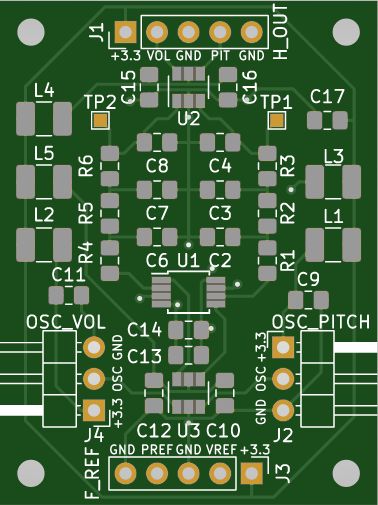
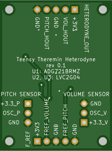
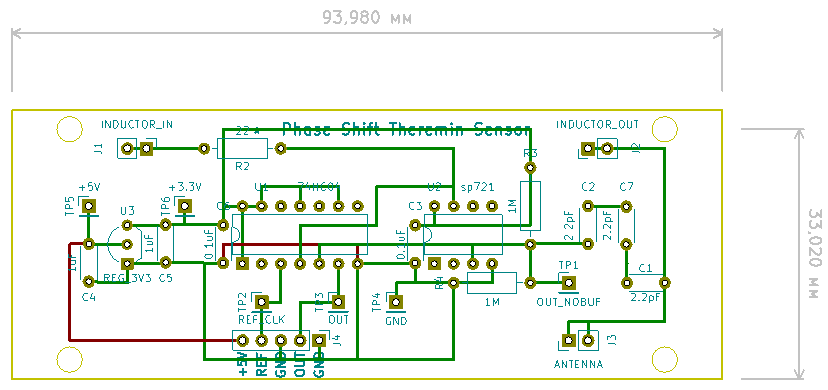
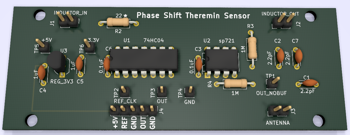
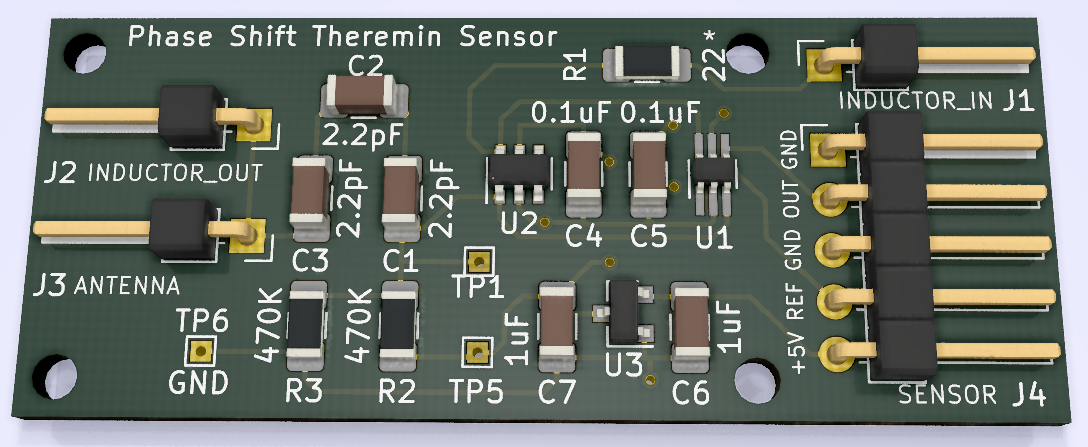
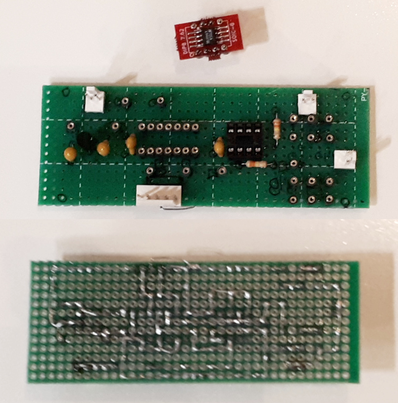
Parts
Theremin cabinets I've built
Plywood laser cut design, inspired by Etherwave

PPL tubes design

Most likely I'll use polypropylene tubes based design, with a bit different layout - with two additional boxes for inductors and oscillators placed near antennas.
Nearest goals
Figure out how to generate synchronous PI/2 phase shifted reference frequency signals on two pins. Which pins to choose?
Does it make sense to solder Audio Adapter upside down to be able accessing its SD card slot from rear panel of device to avoid soldering of additional SD card slot and ribbon cable? Is its performance good enough comparing to true 4-bit SDIO available via ribbon cable?
Does it make sense to write my own audio interface code (e.g. to use 48KHz sample rate and 24 bits per sample), or Audio Library is enough?
Links:
I'm working on my hobby digital theremin project.
Theremin is musical instrument controlled by distance between player's hand and antennas.
In theremin, there are two antennas - one for pitch control and second for volume control. Pitch antenna (right) is usually straight conducting rod, and volume antenna is loop-shaped conducting rod oriented horizontally.
Classic theremins are analog - pitch oscillator frequency is being converted to audible range using heterodyning, and volume antenna cirquit produces volume control voltage to shape pitch signal using VCA.
Digital theremins are actually digital synthesizers controlled by theremin sensors.
This project is started to provide digital theremin design, which is
- Open source, open hardware
- Easy to build
- Low latency of sensors
- Descent synthesizer
- Low cost
Challenges: sensors
When hand approaches antenna, its capacicance increases. Total range of capacitance change due to hand movement is about 1.5pF
Antenna self-capacitance is near 7-8pF. To capture hand movements it's necessary to measure antenna capacitance with very high precision.
C of antenna non-linearly depends on hand range. Each 10cm of additional distance reduce C introduced by hand by ~3.5 times. Required distance measurement precision is about 1mm.
It's easy measure C for short distances - when it changes by 0.1..0.01pF. Even RC based sensor might work on 10cm distance.
But the bigger is distance, the finer resolution of C sensor is needed. Averaging of sensor output could increase precision, but introduces latency.
Good theremin should have low latency (less than 1ms). As bad example of digital theremin sensor design you can try Moog Theremini (latency is 0.1..0.5 seconds!!!)
High precision measurement of C requires LC tank with high Q. L should be big enough (0.5mH..10mH), C should be small (C = C_ant + C_hand + C_internal) to keep good sensitivity.
We can either measure of LC oscillator frequency (1) or measure amplitude or phase shift of reference signal passed through LC (2).
(for reference signal frequency close to LC resonance phase shift is PI/2 and amplitude is max; phase shift is easier to track than amplitude change).
For (1) we have to be able measure frequency with very high precision. LC oscillator frequency (in range 0.2MHz..3Mhz varying by 1..5% depending on hand distance) can be either measured directly (requires very high resolution of measurement timer) or converted to lower frequency higher relative change signal using some heterodyning technique.
In digital theremins (like Open.Theremin) there is often used D-trigger based heterodyne which converts oscillator frequency to easy measurable range. But it has aliasing issues and not enough good performance.
(I've tried this approach in Teensy 3.6 based implementation - it's not precise enough).
For (2) we can convert phase shift to PWM using XOR between LC input and output, convert to voltage using lowpass filter, then measure using ADC.
I've experimented a lot with FPGA based design, where main purpose of FPGA was to implement high precision frequency measure - until I visited pjrc site and found that there is Teensy 4.0 available.
Now I switched to development of digital theremin design based on Teensy 4.0 and Teensy Audio Adaptor (revD).
600/800MHz is more than enough for virtually
Although Teensy 4.0 timer performance is higher than one in Teensy 3.6 (150MHz or even 200MHz overclocked vs 60MHz), it's still not enough for direct measure of oscillator frequency.
Possible solution could be to use external IC like TDC7200, but I'm trying to find some easy to build solution, to minimize soldering while providing high sensitivity and low latency.
Main challenge is design of Pitch antenna sensor able to provide enough bits of distance value for hand distances 80..100cm from antenna.
Phase shift based approach (2) is possible, but requires external ADC (24 bits looks enough according to simulation).
LTSpice model:
LTSpice simulation results - output voltage depending on C_hand with 0.1pF steps:
I hope, this approach can be used for volume antenna where far distances are not required (30..40cm max are usual) - even when measured by Teensy 4.0 internal ADC.
Pitch sensor.
How do we implement sensitive sensor for pitch antenna?
We can go closer to analog theremins.
What if we pass LC oscillator output (F_osc) through heterodyne (mixing with F_ref) to get output signal with frequency F_ref-F_osc?
Oscillator will provide clean sine output. Heterodyne can be built based on analog switch - if F_osc is sampled at F_ref rate and passed through LP filter, output will be clean sine of frequency F_ref-F_osc.
We already have higher precision ADC than one in Teensy 4.0 - it's SGTL5000 from audio board which can provide 16-24 bits once per sample - if Line In of Audio Adaptor is used as ACD.
We only need to make sure that frequency and amplitude of heterodyne output matches Line In capabilities.
How do we measure frequency of heterodyne output? It may vary in amplitude (there is signal damping when hand is close to antenna). Of course, we could detect zero crossings and use interpolation to determine exact time of crossing.
But isn't it possible to have measured value for each sample, not only when signal crosses zero? Tricks with asin() and autocalibration of amplitude, but there is a better way.
Let's use two heterodyne channels, with PI/2 shift between them (use both left and right channels of Line In). In this case we can simple use tan2() on each sample to get phase value signal not dependent on amplitude changes.
We need two reference frequency signals, phase shifted by PI/2, with small duty cycle (0.05..0.2). To achieve this, we can use FlexPWM.
Divider value K for PWM should be divisible by 4 if we need exact PI/2 phase shift. Difference between F_BUS/K and F_BUS/(K+4) should be small enough (e.g. <5KHz) to allow calibration to fit signal in LineIn frequency range.
So, oscillator frequency needs to be < 500KHz.
LTSpice model:
Simulation results - quadrant output to be passed to Audio Adaptor Line In:
Reference frequency signals and oscillator output:
Sensor signal, after calibration, will provide LineIn frequency change F_max-F_min 8..15 KHz where F_min is 1KHz..5KHz depending on calibration results (PWM timer resolution).
In Audio IRQ handler, samples read from LineIn can be converted to phase value, then averaged to reduce noise and increase sensitivity, and then transformed to output note frequency for synthesizer.
For Volume sensor, it's enough to get new value once per audio frame (even after additional filtering/averaging, latency will be good enough - because theremin is less sensitive to volume control latency than to pitch control latency).
Parts
- Teensy 4.0
- Audio Adaptor rev D
- LCD Touch Screen - e.g. from pjrc.com or one from buydisplay.com (on the same ILI chip, same resolution, bigger diagonal, with capacitive touch screen controlled over I2C).
- Two air core inductors (manual winding)
- A few rail-to-rail opamps for sensors.
- Analog switch IC for pitch sensor.
- XOR logic IC for volume sensor.
- Optional SPDIF transmitter module
- Optional SPDIF receiver module
- Optional USB type A socket for usb host
- MicroSD card socket (or just place Audio Adaptor to make its sd card slot available)
- 2-3 incremental oncoders with buttons
- 3-5 pots 10K
- Several audio jacks
- Copper or brass tubes for antennas
- Some box for cabinet
Theremin cabinets I've built
Plywood laser cut design, inspired by Etherwave
PPL tubes design
Most likely I'll use polypropylene tubes based design, with a bit different layout - with two additional boxes for inductors and oscillators placed near antennas.
Nearest goals
Figure out how to generate synchronous PI/2 phase shifted reference frequency signals on two pins. Which pins to choose?
Does it make sense to solder Audio Adapter upside down to be able accessing its SD card slot from rear panel of device to avoid soldering of additional SD card slot and ribbon cable? Is its performance good enough comparing to true 4-bit SDIO available via ribbon cable?
Does it make sense to write my own audio interface code (e.g. to use 48KHz sample rate and 24 bits per sample), or Audio Library is enough?
Links:
- Forum thread on thereminworld.com: Teensy 4.0 600MHz ARM Cortex M-7 MCU - ideal for digital MCU based theremin?
- Project on GitHub: fpga-theremin/theremin
Last edited:


")