Teensy 4.x H/W Quadrature Encoder Library

Sorry for the necro post. Is the right place to ask questions on this library?

I am using QuadEncoder_interrupt_pins. I have changed my HW to use the same pins as the example. Have a couple of questions.

1. In the library, I see that the index counter is defined as uint32_t, but in the running code, an underflow (negative index count) is 16 bits. Why is this? For a motor spinning at 3600 RPM, this would mean rollover ever 18.2 minutes. Is there a way to modify this easily?

2. Is there a way to print out the quad encoder configuration. There's no easy way to determine if the defaults chosen are applicable to the user. I see a method defined, but I don't know how to use it. A minimal example would be helpful. This is not meant as a knock, but if would be really helpful to new users, if there was more documentation, either in the source, or in a wiki. The examples given do not seem to clearly showcase many of the abilities of this library, and it is a bit confusing, at least to me.

3. What is the difference between home and index in a practical sense?

If I were to use this library, I'd like to understand it's practical limitations. What happens when there is a position over or underflow? The HW register is limited to 32 bits. For a motor running continuously, (at high speed) rollover could occur in 19 hours or so, if starting from zero. Practically, I won't run at max speed, but I'd like to be able to handle the situation. There are interrupts defined, but they are disabled, and there is no code. From a practical sense, what might make sense?

My target application is an electronic leadscrew for a lathe, which could be used for cutting threads. I need to work through many of these issues, so that I'm not surprised, or at least I don't cause severe mechanical damage. The main motor is 2 HP, so if things crash, it would not be a good thing.

Thanks for your help.
 
I recommend reading the Quad Decoder (QDC) section of the processor reference manual. This will provide some background when looking at the library source and examples. It looks like the HOME signal can be used to initialize the 32-bit position counters, while the INDEX is for revolution counting. Here's a relevant section. So, the revolution counter in hardware is 16 bits, while it looks to me like the software keeps its own 32-bit revolution count. I only see that value (indexCounter) counting up, while, the index counter in hardware will count up/down.

56.2.3.6 Revolution Counter
The 16-bit up/down revolution counter is intended to count or integrate revolutions by
counting index pulses. The direction of the count is determined by the Count_Up and
Count_Down signals, determined by the Phase A and B inputs. A different count
direction on the rising and falling edges of the index pulse indicates that the quad encoder
changed direction on the index pulse.
 
Thanks for the pointer back to the Manual. Took me a bit to find where I had downloaded it! It defines a couple of things, but it doesn't help too much in understanding the actual library. It did help me understand the difference between the index and home, so that is good.

Is there a way to use the index just as a sanity check that the position count is valid? I think I need the full 32 bits of the position counter, but need a runtime check that there is no pulse accumulation error. Is it possible to have the position counter using 32 bits, but being able to detect the index? If so how?

It's clear I need to delve into this more.

Still don't know how to readback what the configuration settings are which might help me determine if the defaults are even helpful for my use case. Don't like apologizing for this but, it is even hard for me to frame the question with the proper nomenclature to get good answers. My command of C and C++ isn't at the level of the major contributors here. I'm a C in C, if you know what I mean, whereas you are all A's.
 
Thanks for the pointer back to the Manual. It defines a couple of things, but it doesn't help too much in understanding the actual library. It did help me understand the difference between the index and home, so that is good.

Is there a way to use the index just as a sanity check that the position count is valid? I think I need the full 32 bits of the position counter, but need a runtime check that there is no pulse accumulation error. Is it possible to have the position counter using 32 bits, but being able to detect the index? If so how?

My applications don't have a HOME signal, but I think the basic idea is that you have a HOME switch on your machine, and that is input to the Teensy pin defined as the QDC HOME input. That switch defines an absolute position on your lead screw, for example. On power up, depending on whether home is high or low, you move in the direction to change its status, and when you reach HOME, you set your position counter so you have initialized your position and know exactly where the machine is. The INDEX signal, on the other hand, is an output of the encoder, usually labeled M, for Mark or Marker. That is just a one-per-rev signal. Yes, you could use it as a sanity check on your A/B position. Each time you get an INDEX pulse, you could check to see if your A/B count has changed by the expected amount.

Still don't know how to readback what the configuration settings are which might help me determine if the defaults are even helpful for my use case. Don't like apologizing for this but, it is even hard for me to frame the question with the proper nomenclature to get good answers. My command of C and C++ isn't at the level of the major contributors here. I'm a C in C, if you know what I mean, whereas you are all A's.

There is a companion library called EncSim, by the same author I think. I use EncSim to generate simulated encoder signals to controllers in lieu of having an actual machine. You will find example programs where you can create one instance of EncSim and one instance of QuadEncoder. You can set the rate and direction and limits of the encoder signal, i.e. "motion", and that gives you a way to see what happens in the QuadEncoder library. I'll warn you that EncSim has its own learning curve, but it's a good learning tool.

The code below is a sketch that I wrote for bench test. It creates an EncSim (encoder simulator), and gives you the ability to set the encoder PPR via the "ppr" command and to update the output rate via "rpm" or "frq" commands. You can set "rpm" to be positive/negative to reverse direction. This test program just sets speed and direction, but not limits, so it's not everthing you want for your testing, but you can use it as another reference. Perhaps you can combine it with code from the EncSim/QuadEncoder examples. The world of Arduino is full of libraries, some very good ones like these, and some not so good, and almost always less documentation than a new user would like to see.


Code:
#include "EncSim.h"
#include <SerialCommand.h>

EncSim tachsim( 0, 1, 2 );	// pins 0=A, 1=B, 2=M

SerialCommand sCmd;		// SerialCommand object

uint32_t ppr = 1200;			// pulses per rev (*4 for quadrature)
float    rpm = 1000;			// rpm = (60*frq)/(ppr*4)
float    frq = (ppr*4)*(fabs(rpm)/60);	// keep this relationship
bool     update = true;			// update = true to trigger one print

void LED_on();
void LED_off();
void rpmCommand();
void pprCommand();
void frqCommand();
void default_fn( const char *command );
                                 
void setup()
{
  pinMode( LED_BUILTIN, OUTPUT );	// Configure the onboard LED for output
  digitalWrite( LED_BUILTIN, LOW );	// default to LED off

  // Setup callbacks for SerialCommand commands
  sCmd.addCommand( "on",  LED_on );	// Turns LED on
  sCmd.addCommand( "off", LED_off );	// Turns LED off
  sCmd.addCommand( "rpm", rpmCommand );	// rpm followed by new rpm value
  sCmd.addCommand( "ppr", pprCommand );	// ppr followed by new ppr value
  sCmd.addCommand( "frq", frqCommand );	// frq followed by new ppr value
  sCmd.setDefaultHandler( default_fn );	// Handler for command that isn't matched  (says "What?")

  Serial.begin( 115200 );
  delay( 1000 );
  Serial.printf( "Application TachSim0 %s %s\n", __DATE__, __TIME__ );

  tachsim.begin();				// begin()
  tachsim					// CONFIGURATION
  .setPhase( 90 )				// normal 90 deg phase shift
  .setTotalBounceDuration( 0 )			// no bouncing
  .setPeriod( ppr*4 )				// marker every ppr*4 A/B pulses
  .setFrequency( frq );				// frequency = f(ppr,rpm)

  tachsim.setContinuousMode( true );		// don't stop at target
  tachsim.moveRelAsync( rpm >= 0.0 ? +1 : -1 );	// +/- direction
}

void loop()
{
  sCmd.readSerial();
  if (update == true) {
    Serial.printf( "ppr = %4lu   rpm = %6.1f   frq = %8.1f\n", ppr, rpm, frq );
    update = false;
  }
}

void LED_on() { digitalWrite( LED_BUILTIN, HIGH ); }
void LED_off() { digitalWrite( LED_BUILTIN, LOW ); }

void rpmCommand()
{
  char *arg = sCmd.next();
  if (arg == NULL) {
    Serial.println( "No arguments" );
  }
  else {
    rpm = atoi(arg);				// char* to integer
    frq = (ppr*4)*(fabs(rpm)/60);		// compute new frequency
    tachsim.moveRelAsync( rpm >= 0 ? +1 : -1);	// set direction = f(rpm)
    tachsim.setFrequency( frq );		// set frequency
  }
  update = true;
}

void pprCommand()
{
  char *arg = sCmd.next();
  if (arg == NULL) {
    Serial.println( "No arguments" );
  }
  else {
    int temp = atoi(arg);		// char* to integer
    if (temp > 0) {			// if valid ppr
      ppr = temp;			//   set ppr
      frq = (ppr*4)*(fabs(rpm)/60);	//   compute new frequency
      tachsim.setPeriod( ppr*4 );	//   marker every ppr pulses
      tachsim.setFrequency( frq );	//   set frequency
    }
  }
  update = true;
}

void frqCommand()
{
  char *arg = sCmd.next();
  if (arg == NULL) {
    Serial.println( "No arguments" );
  }
  else {
    frq = (float)atoi(arg);		// char* to integer
    rpm = (60*frq)/(ppr*4);		// back-calc rpm
    tachsim.setFrequency( frq );	// set frequency
  }
  update = true;
}

// This gets set as the default handler, and gets called when no other command matches.
void default_fn( const char *command )
{
  Serial.println( "What?" );
}
 
Commented out
Code:
  //myEnc1.EncConfig.IndexTrigger = ENABLE;  //enable to  use index counter
  //myEnc1.EncConfig.INDEXTriggerMode = RISING_EDGE;
This is sort of just trying to understand behaviorally what is happening. As expected, the index counter stays at 0. The position HOLD revolution value increments. The first case is at:
Code:
Current position value1: 114
Position differential value1: 1
Position HOLD revolution value1: 0
Index Counter: 0

Current position value1: 115
Position differential value1: 1
Position HOLD revolution value1: 1
Index Counter: 0
The second increment is at:
Code:
Current position value1: 2246
Position differential value1: 1
Position HOLD revolution value1: 1
Index Counter: 0

Current position value1: 2247
Position differential value1: 1
Position HOLD revolution value1: 2
Index Counter: 0

I do not understand what controls the transition point. I have a 1024 point encoder. So there should be 4096 edges in one full rotation. What is Pulse HOLD revolution doing?
Code:
#include "QuadEncoder.h"


uint32_t mCurPosValue;
uint32_t old_position = 0;
uint32_t mCurPosValue1;
uint32_t old_position1 = 0;
QuadEncoder myEnc1(1, 0, 1, 0, 4);  // Encoder on channel 1 of 4 available
                                   // Phase A (pin0), PhaseB(pin1), Pullups Req(0), Index Z (pin4)
// Allowable encoder pins:
// 0, 1, 2, 3, 4, 5, 7, 30, 31 and 33
                             
void setup()
{
  while(!Serial && millis() < 4000);

  /* Initialize the ENC module. */
  myEnc1.setInitConfig();
  //myEnc1.EncConfig.IndexTrigger = ENABLE;  //enable to  use index counter
  //myEnc1.EncConfig.INDEXTriggerMode = RISING_EDGE;

  myEnc1.init();
  
}

void loop(){
  
  /* This read operation would capture all the position counter to responding hold registers. */
  mCurPosValue = myEnc1.read();

  if(mCurPosValue != old_position){
    /* Read the position values. */
    Serial.printf("Current position value1: %ld\r\n", mCurPosValue);
    Serial.printf("Position differential value1: %d\r\n", (int16_t)myEnc1.getHoldDifference());
    Serial.printf("Position HOLD revolution value1: %d\r\n", myEnc1.getHoldRevolution());
    Serial.printf("Index Counter: %d\r\n", myEnc1.indexCounter);
    Serial.println();
  }

  old_position = mCurPosValue;

}
 
The world of Arduino is full of libraries, some very good ones like these, and some not so good, and almost always less documentation than a new user would like to see.
Isn't that the truth! It really is an impediment to new users. Kind of a barrier to entry.
 
I remember being very confused when I first started trying to use QuadEncoder. The HOLD registers are simply a "snapshot" of what was in various registers at the time that a read() was executed. This is done in hardware so that you get a coherent set of values. See section 56.4 for a description of the signals. The QDC module has a LOT of features, way more than you'll need, and the library supports a lot of them, so the learning curve is steep. Read the manual and then go back to the examples.
 
Thanks for the tip on EncSim. I will take a look at it.

The Arduino world is relatively easy to get into, but really hard to unravel the gory details without a lot of work and sweat. If you need to do something other than pedestrian, it can be quite difficult to get to the meat of it at times. A couple of years ago I made a doppler radar chronograph using an Feather M4. Was totally unaware of Teensy's at the time. The radar signal processing for me was easy - I knew how to do it, but getting the ADC, the DMA, and CMSIS 1K FFTs to run continuously at 50 Hz was a pain. As was writing to a tft display. Spent more time on the tft than the whole signal processing chain! To be honest, the display and touch panel needs some more work there. But this is a digression, this thread is on using the HW Quad Encoder Library.
 
I remember being very confused when I first started trying to use QuadEncoder. The HOLD registers are simply a "snapshot" of what was in various registers at the time that a read() was executed. This is done in hardware so that you get a coherent set of values. See section 56.4 for a description of the signals. The QDC module has a LOT of features, way more than you'll need, and the library supports a lot of them, so the learning curve is steep. Read the manual and then go back to the examples.

Back to the books... Will do that.
Still hard for me to comprehend what can cause this kind of output.
Code:
Current position value1: 4377
Position differential value1: -1
Position HOLD revolution value1: 2
Index Counter: 0

Current position value1: 4376
Position differential value1: -1
Position HOLD revolution value1: 2
Index Counter: 0

Current position value1: 4377
Position differential value1: 1
Position HOLD revolution value1: 2
Index Counter: 0

Current position value1: 4376
Position differential value1: -1
Position HOLD revolution value1: 31
Index Counter: 0

Current position value1: 4377
Position differential value1: 1
Position HOLD revolution value1: 30
Index Counter: 0
Doesn't feel causal for the Pos HOLD rev value to go from 2 to 31 with a position value from 4377 to 4376!
This makes me feel something is wrong, really wrong. It may not be, but it doesn't make sense to me at all. This is with a real rotary encoder, sitting on my desk.
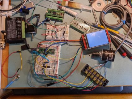
PXL_20220510_175312263_500.jpg
 
See the printConfig() method.

Maybe I'm a dunce, but I don't know how to invoke it. myEnc1.printConfig(); Gives me a compile error. Error is "no matching function for call to 'QuadEncoder::printConfig();'
Ah. I have a library problem.
Code:
Arduino: 1.8.19 (Linux), TD: 1.56, Board: "Teensy 4.1, Serial, 600 MHz, Faster, US English"

QuadEncoder_Interrupt_pins__bdl: In function 'void setup()':
QuadEncoder_Interrupt_pins__bdl:23: error: no matching function for call to 'QuadEncoder::printConfig()'
   myEnc1.printConfig();
                      ^
In file included from /home/me/Arduino/QuadEncoder_Interrupt_pins__bdl/QuadEncoder_Interrupt_pins__bdl.ino:1:0:
/home/me/Apps/arduino-1.8.19/hardware/teensy/avr/libraries/QuadEncoder/QuadEncoder.h:196:7: note: candidate: void QuadEncoder::printConfig(QuadEncoder::enc_config_t*)
  void printConfig(enc_config_t *config);
       ^
/home/me/Apps/arduino-1.8.19/hardware/teensy/avr/libraries/QuadEncoder/QuadEncoder.h:196:7: note:   candidate expects 1 argument, 0 provided
Multiple libraries were found for "QuadEncoder.h"
 Used: /home/me/Apps/arduino-1.8.19/hardware/teensy/avr/libraries/QuadEncoder
 Not used: /home/me/Arduino/libraries/Teensy-4.x-Quad-Encoder-Library-master
no matching function for call to 'QuadEncoder::printConfig()'

This report would have more information with
"Show verbose output during compilation"
option enabled in File -> Preferences.
What is a good way to fix the libraries? And how is the method invoked?

edit: Apparently this is a known Arduino issue. How do I find out which is more current?
 
Last edited:
Maybe I'm a dunce, but I don't know how to invoke it. myEnc1.printConfig(); Gives me a compile error. Error is "no matching function for call to 'QuadEncoder::printConfig();'
Ah. I have a library problem.

What is a good way to fix the libraries? And how is the method invoked?

It gets invoked this way:
Code:
 myEnc1.printConfig(&myEnc1.EncConfig);

which will print out something like:
Code:
	enableReverseDirection: 0
	decoderWorkMode: 0
	HOMETriggerMode: 0
	INDEXTriggerMode: 0
	IndexTrigger: 0
	HomeTrigger: 0
	clearCounter: 0
	clearHoldCounter: 0
	filterCount: 0
	filterSamplePeriod: 0
	positionCompareValue: ffffffff
	revolutionCountCondition: 0
	enableModuloCountMode: 0
	positionInitialValue: 0
	positionROIE: 0
	positionRUIE: 0
and before you ask if you look at the readme for the library it will give you the definitions for the library config items: https://github.com/mjs513/Teensy-4.x-Quad-Encoder-Library.

Unfortunately don't have my "real" encoder handy right now so can't duplicate what you are seeing.
 
I'm not sure why you say you have a library problem. TeensyDuino 1.57b1 is available, but I think you're okay with 1.56. Here is the declaration of the printConfig() function. The argument is a pointer to a structure of type "enc_config_t", which is defined in QuadEncoder.h. The QuadEncoder class contains a static member "enc_config_t EncConfig", and you will see that referenced below.

Code:
void printConfig(enc_config_t *config);

Since you're using the example QuadEncoder_Interrupt_pins, I'll show the initialization code from that example.

Code:
  /* Initialize the ENC module. */
  myEnc1.setInitConfig();
  myEnc1.EncConfig.INDEXTriggerMode = RISING_EDGE;
  myEnc1.init();

- 1st line calls myEnc1.setInitConfig() to set the EncConfig structure to defaults
- 2nd line sets a field of myEnc1.EncConfig to a non-default value
- 3rd line calls myEnc1.init() which configures the QDC registers according to the contents of EncConfig

If you want to set additional fields to non-default values, and you probably do, you do that between the 2nd and 3rd lines. In other words, you set the fields of EncConfig the way you want, and then you call the init() function to "map" those settings onto the actual QDC peripheral registers.

At any time before or after the call to myEnc1.init(), you can add the line below to print the contents of EncConfig. Remember, though, this is just a data structure within the QuadEncoder class. You haven't actually initialized the QDC peripheral on the chip until you call myEnc1.init(), so I would recommend calling it after myEnc1.init(), just to avoid confusion.

Code:
  myEnc1.printConfig( &myEnc1.EncConfig );

Since you're not a C++ programmer (yet), I'll mention that since EncConfig is a "static" member of the QuadEncoder class, there is just one instance of that structure for all instances of the class. In other words, if you have multiple encoders, and you want to set them up the same way, you can set the fields of myEnc1.EncConfig, then call myEnc1.init() and myEnc2.init() to set them both up the same way.

I'm not that much of a C++ programmer, so I hope all of that is correct.
 
@joepasquariello
Thats a great explanation - and yes thats my interpretation.

Since printconfig is rarely used (anyway no one has asked) I went back to double check if it was printing the values out correctly and found an error in a couple of the print statements - they were pointing to the wrong values that you set. I am going to push a change to the library in a bit but if you are comfortable you change the current printconfig function to:
Code:
void QuadEncoder::printConfig(enc_config_t *config)
{
	Serial.printf("\tenableReverseDirection: %d\n",config->enableReverseDirection);
	Serial.printf("\tdecoderWorkMode: %d\n",config->decoderWorkMode);
	Serial.printf("\tHOMETriggerMode: %d\n",config->HOMETriggerMode);
	Serial.printf("\tINDEXTriggerMode: %d\n",config->INDEXTriggerMode);
	Serial.printf("\tIndexTrigger: %d\n",config->IndexTrigger);
	Serial.printf("\tHomeTrigger: %d\n",config->HomeTrigger);	
	
	Serial.printf("\tclearCounter: %d\n",config->clearCounter);
	Serial.printf("\tclearHoldCounter: %d\n",config->clearHoldCounter);
	
	Serial.printf("\tfilterCount: %d\n",config->filterCount);
	Serial.printf("\tfilterSamplePeriod: %d\n",config->filterSamplePeriod);
	Serial.printf("\tpositionCompareValue: %x\n",config->positionCompareValue);
	Serial.printf("\trevolutionCountCondition: %d\n",config->revolutionCountCondition);
	Serial.printf("\tenableModuloCountMode: %d\n",config->enableModuloCountMode);
	Serial.printf("\tpositionModulusValue: %d\n", config->positionModulusValue);
	
	Serial.printf("\tpositionInitialValue: %d\n",config->positionInitialValue);
	Serial.printf("\tpositionROIE: %d\n",config->positionROIE);
	Serial.printf("\tpositionRUIE: %x\n",config->positionRUIE);
	Serial.printf("\n");
}
 
Thanks for helping out with the invocation. That helps! I've spent a lot of time on your github link. Basic problem - I'm a lousy C programmer, who has to persevere nonetheless. I do a lot better with Scipy & Numpy than C, but that's of little help here. Don't think I would have guessed that way, although now doing a search for that, it makes sense. Thanks.
 
Thanks for helping out with the invocation. That helps! I've spent a lot of time on your github link. Basic problem - I'm a lousy C programmer, who has to persevere nonetheless. I do a lot better with Scipy & Numpy than C, but that's of little help here. Don't think I would have guessed that way, although now doing a search for that, it makes sense. Thanks.

Not a problem considering I am not the greatest either I do better with c++ than numpy or scipy - its all a learning exercise.
 
My exposure to C++ was a little harsh. I had written a client & server program for an FFT engine and prototyped it in Numpy. Got it all running (both ends, client and server) and then had to port the server to C++ for "some additional speed". Since I had used object oriented programming (in python), the port from python to C++ took me 1 day. I got stuck on one C++ thing and had to learn about friends. But that really was it for my C++ experience, and that was well over 12 years ago. These languages require constant exposure, or you forget most of it.

As for the printConfig method - yes, it isn't that revealing. But it did help me learn a little. I was mostly struggling with what the heck the name of the thing was. Must have stared at both the header and source files for 45 minutes looking for the magic name to use. It just didn't pop out at me.
 
I'm not sure why you say you have a library problem. TeensyDuino 1.57b1 is available, but I think you're okay with 1.56. Here is the declaration of the printConfig() function. The argument is a pointer to a structure of type "enc_config_t", which is defined in QuadEncoder.h. The QuadEncoder class contains a static member "enc_config_t EncConfig", and you will see that referenced below.

Code:
void printConfig(enc_config_t *config);

Since you're using the example QuadEncoder_Interrupt_pins, I'll show the initialization code from that example.

Code:
  /* Initialize the ENC module. */
  myEnc1.setInitConfig();
  myEnc1.EncConfig.INDEXTriggerMode = RISING_EDGE;
  myEnc1.init();

- 1st line calls myEnc1.setInitConfig() to set the EncConfig structure to defaults
- 2nd line sets a field of myEnc1.EncConfig to a non-default value
- 3rd line calls myEnc1.init() which configures the QDC registers according to the contents of EncConfig

If you want to set additional fields to non-default values, and you probably do, you do that between the 2nd and 3rd lines. In other words, you set the fields of EncConfig the way you want, and then you call the init() function to "map" those settings onto the actual QDC peripheral registers.

At any time before or after the call to myEnc1.init(), you can add the line below to print the contents of EncConfig. Remember, though, this is just a data structure within the QuadEncoder class. You haven't actually initialized the QDC peripheral on the chip until you call myEnc1.init(), so I would recommend calling it after myEnc1.init(), just to avoid confusion.

Code:
  myEnc1.printConfig( &myEnc1.EncConfig );

Since you're not a C++ programmer (yet), I'll mention that since EncConfig is a "static" member of the QuadEncoder class, there is just one instance of that structure for all instances of the class. In other words, if you have multiple encoders, and you want to set them up the same way, you can set the fields of myEnc1.EncConfig, then call myEnc1.init() and myEnc2.init() to set them both up the same way.

I'm not that much of a C++ programmer, so I hope all of that is correct.

Thanks for your explanation. This is very helpful to someone like me. Although it is a simple explanation, it confirms much of what I was thinking.
 
@joepasquariello apparently I had two versions of the library, one in /arduino/hardware and another local library in my sketch area. The compiler was issuing a warning. I deleted the one in the sketch area and left the system one.
 
Quad encoder low speed measurement

Hi everyone,

I am still struggling with the issue of wanting to measure the time between two consecutive edges of Phase A and Phase B of a quadrature encoder connected to a Teensy 4.1.

In the IMXRT1060RT reference manual in Chapter 56.3, Table 56-2 it says:
The PHASEA input can be an input capture channel for one of the timer
modules (in the SoC), which can be connected to using a crossbar switch.
This is exactly what I want but I have no idea how to get there. (The same applies to Phase B)

Maybe some general questions first:
  • The Quad encoder library by mjs513 "only" allows certain physical Teensy pins to be used with the Quad Encoder/Decoder module of the IMXRT1062 micro controller used in the Teensy 4.1.
    Q: Is this a restriction by the library itself or due to the hardware layout?

  • My understanding is that the crossbar switch seems to be a very powerful feature of this mcu, which allows routing signals, applied to external physical pins, to different peripherals/modules such as timers. It might also allow internal routing of signals between different peripherals.
    Q: Is it correct that the flexibility this provides is however hardware-limited, meaning that not any input of any peripheral can be routed to any other output of any other peripheral?
    Q: Is this restriction (if it exists) reflected by Tables 4.5 - 4.10 in Chapter 4.6 of the reference manual?

In my specific case, Phase A and B are connected to Teensy pins 5 and 7, respectively. I would like both signals to trigger an input capture event of a timer so I can measure the time between two consecutive edges of Phase A and B.
I think my main problem is the lacking of a good understanding of the crossbar switch and possibly the IOMUX, besides being new to mcu programming of course ;)
Is it just me or are the Atmel/Microchip data sheets easier to read and understand in comparison to the ones from NXP?
Any hints (further reading, code examples, etc.) are much appreciated.

Cheers, Matt
 
@mattjowil
I can try to answer your questions but may be confusing:
The Quad encoder library by mjs513 "only" allows certain physical Teensy pins to be used with the Quad Encoder/Decoder module of the IMXRT1062 micro controller used in the Teensy 4.1.
Q: Is this a restriction by the library itself or due to the hardware layout?
Its a restriction based on the IMXRT1060 itself. The Encoder module is dependent on using XBAR (See figure 56-1) to access the physical pins on the T4 so only pins that have cross bar assignments in their IOMUX MUX_MODE can be used for instance for Pin 0 which is AD_B0_03 has the following assignment (see page 477):
Code:
001 ALT1 — Select mux mode: ALT1 mux port: XBAR1_INOUT17 of instance: xbar1
which the library uses. So not any pin can be used. In addition if 2 pins share the same XBAR1_INOUTXX they can not be used together other wise there will be a conflict.

My understanding is that the crossbar switch seems to be a very powerful feature of this mcu, which allows routing signals, applied to external physical pins, to different peripherals/modules such as timers. It might also allow internal routing of signals between different peripherals.
Q: Is it correct that the flexibility this provides is however hardware-limited, meaning that not any input of any peripheral can be routed to any other output of any other peripheral?
Q: Is this restriction (if it exists) reflected by Tables 4.5 - 4.10 in Chapter 4.6 of the reference manual?
Think I may have touched on this in my previous answer. As for table 4.5-4.10 I am using table 4.8 for the OUT values. I don't believe its clear just by looking at the tables as they are linked with pins etc.

If you look in the library you are going to see a rather convoluted process of assigning pin numbers, and xbar assignments.

The following table in the library:
Code:
const QuadEncoder::ENC_Channel_t QuadEncoder::channel[] = {	
	{0,&IMXRT_ENC1, IRQ_ENC1, isrEnc1, 66, 67, 68, 69, 70,&CCM_CCGR4,CCM_CCGR4_ENC1(CCM_CCGR_ON)},  //this is a dummy entry - use 1-4 for channels
	{1, &IMXRT_ENC1, IRQ_ENC1, isrEnc1, 66, 67, 68, 69, 70,&CCM_CCGR4,CCM_CCGR4_ENC1(CCM_CCGR_ON)},
	{2, &IMXRT_ENC2, IRQ_ENC2, isrEnc2, 71, 72, 73, 74, 75,&CCM_CCGR4,CCM_CCGR4_ENC2(CCM_CCGR_ON)},
	{3, &IMXRT_ENC3, IRQ_ENC3, isrEnc3, 76, 77, 78, 79, 80,&CCM_CCGR4,CCM_CCGR4_ENC3(CCM_CCGR_ON)},
	{4, &IMXRT_ENC4, IRQ_ENC4, isrEnc4, 81, 82, 83, 84, 95,&CCM_CCGR4,CCM_CCGR4_ENC4(CCM_CCGR_ON)}
implements table 4.8 requirements and the layout is defined as:
Code:
	//encoder
	typedef struct {
		uint8_t			enc_ch;		
		volatile IMXRT_ENC_t* 	ENC;
		IRQ_NUMBER_t	interrupt;
		void     		(*isr)();
		uint16_t		phaseA;
		uint16_t		phaseB;
		uint16_t		index;
		uint16_t		home;
		uint16_t		trigger;
		volatile uint32_t *clock_gate_register;
		uint32_t 		clock_gate_mask;
	} ENC_Channel_t;

then in the library
Code:
//xbara1 pin config
// idx, pin, *reg, alt,xbarIO, xbarMUX

#if defined( ARDUINO_TEENSY40)
const  QuadEncoder::ENC_Hardware_t QuadEncoder::hardware[] = {	
	{0, 0, &CORE_XIO_PIN0, 1, 17, 1},	{1, 1, &CORE_XIO_PIN1, 1, 16, 0},
	{2, 2, &CORE_XIO_PIN2, 3, 6, 0},	{3, 3, &CORE_XIO_PIN3, 3, 7, 0},
	{4, 4, &CORE_XIO_PIN4,3, 8, 0},		{5, 5, &CORE_XIO_PIN5, 3, 17, 0},
	{6, 7, &CORE_XIO_PIN7, 1, 15, 1},	{8, 8, &CORE_XIO_PIN8, 1, 14, 1},
	{8, 30, &CORE_XIO_PIN30, 1, 23, 0},	{9, 31, &CORE_XIO_PIN31, 1, 22, 0},
	{10, 33, &CORE_XIO_PIN33, 3, 9, 0}
};
provides the cross walk between pins and xbar io mux assignments.

The library has two functions that perform the work to so the final xbar mapping and make the correct connections.
Code:
	//xbara1 configuration
	void enc_xbara_mapping(uint8_t pin, uint8_t PHASE, uint8_t PUS);
	void xbar_connect(unsigned int input, unsigned int output);
 
@mjs513 Thank you for the quick answer.
It's late already but one thing caught my attention:
Shouldn't the highlighted, red "95" not be "85"?

Code:
const QuadEncoder::ENC_Channel_t QuadEncoder::channel[] = {	
	{0,&IMXRT_ENC1, IRQ_ENC1, isrEnc1, 66, 67, 68, 69, 70,&CCM_CCGR4,CCM_CCGR4_ENC1(CCM_CCGR_ON)},  //this is a dummy entry - use 1-4 for channels
	{1, &IMXRT_ENC1, IRQ_ENC1, isrEnc1, 66, 67, 68, 69, 70,&CCM_CCGR4,CCM_CCGR4_ENC1(CCM_CCGR_ON)},
	{2, &IMXRT_ENC2, IRQ_ENC2, isrEnc2, 71, 72, 73, 74, 75,&CCM_CCGR4,CCM_CCGR4_ENC2(CCM_CCGR_ON)},
	{3, &IMXRT_ENC3, IRQ_ENC3, isrEnc3, 76, 77, 78, 79, 80,&CCM_CCGR4,CCM_CCGR4_ENC3(CCM_CCGR_ON)},
	{4, &IMXRT_ENC4, IRQ_ENC4, isrEnc4, 81, 82, 83, 84, [COLOR="#FF0000"][B]95[/B][/COLOR],&CCM_CCGR4,CCM_CCGR4_ENC4(CCM_CCGR_ON)}

Cheers,
Matt

Yep - should be 85 - good catch and good eye :) Will fix
 
I want to use the QuadEncoder + Interrupts on PinA and PinB. It seems that switsching the Pins (2 and 3) with the XBAR to the encoder disabled the interrupts and vice versa, attaching interrupts to the Pins, disables the QuadEncoder. The later blocks the former.

Any idea to habe Filtering of the QuadEncoder and Interrupt response on the signal transition (without applying the signal to two Pins)?

Best regards

Edmund
 
Back
Top