Newbie alert ! ;-) Trying to use WS2811 Library - BasicTest - Lights don't come on

Status
Not open for further replies.

LedSled

Member
Hi! :)

I am looking for a little help and I am brand-new to using a microcontroller with LEDs

I am using this hardware:
WS2815 LEDs use a blue wire for "data", green for "backup data"; I have BU & GN connected together.

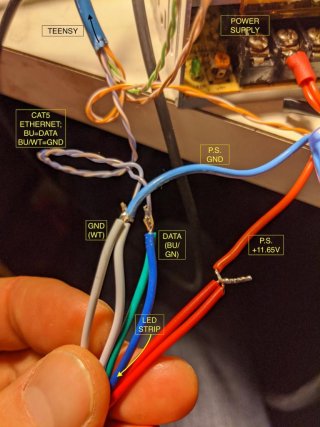
Red is "12V" and verified with DMM (digital multimeter); connected to '+'

White is "GND" and verified with DMM; connected to '-'

I have 11.65VDC at the lightstrip.

Teensy is connected to my computer and the Octo WS2811 adapter board.

Ethernet cable (CAT5) is wired thusly:
BU (Blue) = DATA
BU/WT (Blue/White) = GND

I am using the Library in the Arduino IDE Examples called "WS2812Serial/BasicTest"

I see in the code the options to use any of these pins:
1, 5, 8, 10, 31*
*I tried all of these pins, in both of the RJ45 jacks.

The Teensy appears to be working correctly. For example, I was able to modify and test the standard basic "Blink" program

Any ideas on what to check next?

thanks,
Scott
 
Hey! Thanks so much for the reply.

Let me know if this looks OK?
 

Attachments

  • IMG_20191215_040309.jpg
    IMG_20191215_040309.jpg
    92.8 KB · Views: 92
It has been a long time since I played with some of these LED strips, but if I remember correctly these strips have an input side and an output side (the side that can connect to the input of the next set of LEDS...)

So are you connecting the Teensy to the correct end of the strip?
 
Also do a check (with power off) with your multimeter in ohms mode to check the white/blue wire really is ground. Some CAT5 cables have the colors swapped.
 
Does blue on a standard ethernet cable correspond to a valid ws2812Serial pin on the octows2811 board?
 
It has been a long time since I played with some of these LED strips, but if I remember correctly these strips have an input side and an output side (the side that can connect to the input of the next set of LEDS...)

So are you connecting the Teensy to the correct end of the strip?

Have to check that!

I did just check the WT/BU is ground - verified.

Gibbedy - the ethernet blue is wired for this adapter board:
https://www.pjrc.com/store/octo28_adaptor.html

per this reference:
https://www.pjrc.com/teensy/pinout.html

for Teensy 3.2 (what I have), it should be Serial on pins 1,5,8,10 (why does it also identify '31' in the example code?)
 
I swapped the connection at the LED Strip to the opposite end.

Same behavior (nothing).

Then I re-terminated the Ethernet cable with a new RJ45 Connector.

1) At first LED #1 came on, in a white color.
2) Then I tried the other pins in the code example, and connecting the RJ45 connector to each of the two jacks on the octo adapter board. Code never does anything.

Randomly, some other lights on the string came on (~10), a few green, a few blue, some pinkish. All random seeming.

Going to try some other CAT5 cables and verify with a cable tester.
 
Again pardon that I am not an expert in this, but maybe if you explain your setup, including the example sketch you are using, it might help to understand what may be happening.

That is you mention the ws2812Serial library, and pins valid for the library...

And you mention the hardware Octo WS2811,

So how is this all connected? Do you have the T3.2 plugged into Octo board? If so I am not sure how the Serial library works, as instead of driving all 8 IO pins that are connected to the OCTO board, which I believe are: 2, 14, 7, 8, 20, 21, 5, which then go through to the 8 signals coming out of the 74HCT245 board, you have just one coming out of one of the Serial ports...

Again Valid Uart TX pins on T3.2 are 1, 5, 8, 10, 31 - Note pins 5 and 31 are alternate (setTX) pins...

SO if you have T3.2 plugged directly into Octo the only pin in common is pin 8.

Which if I am guessing correctly translates to the 4th output of the OCTO board or probably the Brown wire... But again I could be completely wrong.
 
Going to try some other CAT5 cables and verify with a cable tester.

A very simple test you can with only a voltmeter is to run the LED blink example (File > Examples > 01.Basics > Blink) and edit the pin number. Then watch if the voltage on the blue wire toggles between 0 to 3.3V every second.

You could also try sharing more photos. As I said earlier, we can help much more if we're able to see. So far, the only part we're able to see if just a few solder connections, but not where those wires really connect and how all the rest of your system is connected.
 
Progress is being made!

Kurt, you are onto something, I think.

Also, I can't upload photos easily on mobile(?) so I will get more as soon as I bring my computer back to the workshop.

Today I did the following:
I replaced the ethernet cable with another one that I verified was OK (connecting two computers), before cutting it in half and using it to solder to the LED Strips.

I connected eight strips of 8 LEDs each, with all power and and grounds connected to +, - on the power supply, respectively. I then hooked up the eight data (DI;"Data IN" I take it ;) ) wires (solid color orange, blue, green, brown) to the eight LED Strips. Connected like the demo on the WS2811 Octo adapter board page.

When I use the "upper" RJ45 port on the octo board (ethernet cables pointing right), and I select 'pin 8' in the WS2812 library/BasicTest, we have action! The LEDs stream colors and switch every ~1.5sec.

Also, when I use the "lower" RJ45 port and select 'pin 5' in the WS2812/BasicTest, I get action there, on the same exact strip (and only that strip).

At all times, the other 7 strips of LEDs are lit random colors (once), but they don't change colors:)confused:)

I will bring my computer so I can share more photos.

Thanks for your response.
Scott
 
Sounds like it’s working fine unless I misunderstand your description. Why don’t you use the octows2811 library when using the octows2811 board. Then all your pins would work.
 
and it works!

Thank you all! I am grateful for you pointing me in the right direction at this early stage of my knowledge.
 
Status
Not open for further replies.
Back
Top