Teensy 4.0 "5V in" not the same as "USB 5V in"? (no MQS Audio output)

Status
Not open for further replies.

Utak

Active member
Teensy 4.0 "5V in" not the same as "USB 5V in"? (no MQS Audio output)

Is there a difference between USB 5V and 5V in Pin?

I'm using the MQS Audio Out Pins, but these Pins working with USB 5V only.

At least they seem to need the USB 5V for "starting". Because if I cut off the USB 5V after boot... the Audio is working (with also 5V on the Pin "5V in" ).


Curious. Is there a workaround for this bug?

I found more differences... if I use the USB 5V Input the LED (Pin 13) is not going on (correct). But if I use the "5V in" Pin, then the LED (Pin13) is on. Also curious
 
Is there a difference between USB 5V and 5V in Pin?

By default they're connected together, so there's no difference unless you've cut apart the VUSB-VIN pads on the bottom side of the board. See the schematic for details:

https://www.pjrc.com/teensy/schematic.html


I'm using the MQS Audio Out Pins, but these Pins working with USB 5V only.

At least they seem to need the USB 5V for "starting". Because if I cut off the USB 5V after boot... the Audio is working (with also 5V on the Pin "5V in" ).

Curious. Is there a workaround for this bug?

I really have no idea what you're talking about. I'm can see what you're really doing, not to mention having a clear enough picture to reproduce it here.

There isn't any known bug that's anything like what you've described, and those pins are 3.3V only, no 5V, so most of this just doesn't make any sense to me at all.

I'm not trying to deny there many indeed be a bug. But if there is, it's unknown (at least to me). As a general rule, I only investigate bug reports when there's enough info to reproduce the bug. For a case like this, the exact code you're running, a list of the exact libs used (if not libs Teensyduino installs), and clear photos showing exactly how you've wired the hardware would be a bare minimum.
 
I've cut apart the VUSB-VIN pads. Now it is working fine. Maybe I've missed something. I don't know.

But what is this curious LED state? With USB Power the LED is off, without the LED goes on.

Btw. thanks for the fast response, world record ;-)
 
Is there a difference between USB 5V and 5V in Pin?

I'm using the MQS Audio Out Pins, but these Pins working with USB 5V only.

At least they seem to need the USB 5V for "starting". Because if I cut off the USB 5V after boot... the Audio is working (with also 5V on the Pin "5V in" ).


Curious. Is there a workaround for this bug?

I found more differences... if I use the USB 5V Input the LED (Pin 13) is not going on (correct). But if I use the "5V in" Pin, then the LED (Pin13) is on. Also curious

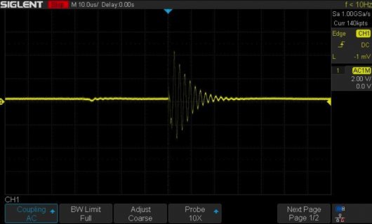
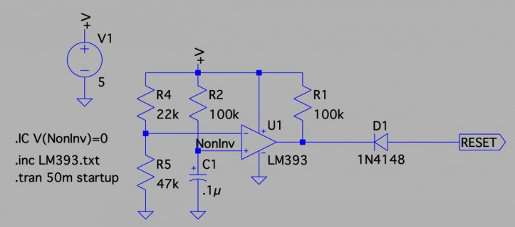
Taking a shot in the dark here. Are you using a bench power supply? And is it the case that your configuration works OK when starting with USB power but not with the bench power supply? But that if you start with USB connected and then disconnect USB but with the bench supply connected things continue to work just fine? If so, then I have noticed that bench power supplies commonly start up with a ringing effect on the output while the control loop gets a grip on proceedings, this is shown in my scope screen capture. That voltage fluctuation I have known to disrupt the initialisation of microcontrollers such that the loaded sketch will not run. My answer is to use a power on reset circuit, also shown, with all my projects; it holds Reset low for 10ms while the power supply sorts itself out but does not interfere with programming as just hanging a capacitor on Reset will do.

If none of this is relevant then please forgive an old man's rambling.

ringing.jpg

reset.jpg
 
Thanks. Good info. Bench Power supply + Reset: yes, something similar :)

I think that it is, if the VUSB-VIN pads were not cut apart. But I've cut apart the VUSB-VIN pads... and now it's working fine.
 
Last edited:
Status
Not open for further replies.
Back
Top