This is a purely research question, not tech support, but I'm hoping it's interesting to someone on this forum. I've read the Bounce2 library and various others, and TBH, in practice I've found that a simple delay debounces well enough for my applications.
But I wanted to play with hardware debouncing, and this is my progress. I've been trying to learn more about bouncy buttons and hardware debouncing.
I wired a noisy button into my oscilloscope and a T4. The button is pulled up to 3.3v through 4.7K, with the other leg to gnd + the oscope's CH1 + pin14 on the T4 + and pin 1A on a 74HC14 inverting Schmitt trigger.
The 74HC14's corresponding 1Y pin goes to the T4's pin15 + the oscope's CH2.
In the sketch (attached), both pin14 and pin15 are attached to interrupts and count transitions; a third count puts a 200ms debouncing delay on the button's signal and counts.
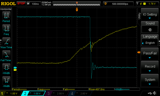
About half the time, a press results in an transition like the one in the image below and an increment of 1 on all 3 counts.

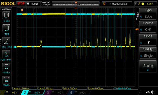
But every 5-10 presses, the button goes bounce-tastic, like this:

On that incident, in 14ms there were 36 rising edges counted on the button's pin and 34 falling edges on the pin connected to the 74HC14's output. The timescale is 200us/div, so only the first bounces can be seen in the image.
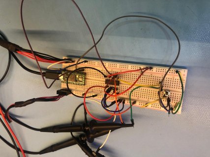
I've attached a photo of my wiring and the code used to count button transitions.
Questions:
1) Am I setting up a test of debouncing correctly? what other stuff should I look at?
2) The bounce patterns I'm seeing with this and other buttons don't look like other bouncy measures I've seen in various tutorials. In particular, the bouncing seems to happen much faster and settle more quickly -- on the order of us, not ms. This leads back to Q1: am I measuring correctly?
3) I put an RC filter on the switch. I didn't show it here because it worked as expected: a single smooth rise, the 74HC14 creates a square transition exactly at the expected point, and the T4 counts each press only once.
What other wiring + oscope study would illuminate contact noise? Thanks for any suggestions -- wylbur.

But I wanted to play with hardware debouncing, and this is my progress. I've been trying to learn more about bouncy buttons and hardware debouncing.
I wired a noisy button into my oscilloscope and a T4. The button is pulled up to 3.3v through 4.7K, with the other leg to gnd + the oscope's CH1 + pin14 on the T4 + and pin 1A on a 74HC14 inverting Schmitt trigger.
The 74HC14's corresponding 1Y pin goes to the T4's pin15 + the oscope's CH2.
In the sketch (attached), both pin14 and pin15 are attached to interrupts and count transitions; a third count puts a 200ms debouncing delay on the button's signal and counts.
About half the time, a press results in an transition like the one in the image below and an increment of 1 on all 3 counts.

But every 5-10 presses, the button goes bounce-tastic, like this:

On that incident, in 14ms there were 36 rising edges counted on the button's pin and 34 falling edges on the pin connected to the 74HC14's output. The timescale is 200us/div, so only the first bounces can be seen in the image.
I've attached a photo of my wiring and the code used to count button transitions.
Questions:
1) Am I setting up a test of debouncing correctly? what other stuff should I look at?
2) The bounce patterns I'm seeing with this and other buttons don't look like other bouncy measures I've seen in various tutorials. In particular, the bouncing seems to happen much faster and settle more quickly -- on the order of us, not ms. This leads back to Q1: am I measuring correctly?
3) I put an RC filter on the switch. I didn't show it here because it worked as expected: a single smooth rise, the 74HC14 creates a square transition exactly at the expected point, and the T4 counts each press only once.
What other wiring + oscope study would illuminate contact noise? Thanks for any suggestions -- wylbur.

Code:
/*
   testing button press counts
   wylbur, 25 Dec 2019
*/

const int BUTTON_PIN = 14;
const int CHIP_PIN = 15;

int chip_count = 0;
int button_count = 0;
int delay_button_count = 0;
int last_button_count = 0;
long time_at_last_press = 0;

void setup() {
  Serial.begin(57600);

  pinMode(BUTTON_PIN, INPUT_PULLUP);
  pinMode(CHIP_PIN, INPUT_PULLUP);

  attachInterrupt(digitalPinToInterrupt(BUTTON_PIN), isrButton, RISING);
  attachInterrupt(digitalPinToInterrupt(CHIP_PIN), isrChip, FALLING);

  time_at_last_press = millis();
  Serial.println("init complete.");
}

void loop() {

  if (button_count != last_button_count) {
     Serial.print(millis());
     Serial.print(F(": button="));
     Serial.print(button_count);
     Serial.print(F(", delay_button_count="));
     Serial.print(delay_button_count);
     Serial.print(F("; chip="));
     Serial.println(chip_count);

     last_button_count = button_count;
  }

}

void isrButton() {
  button_count++;
  if (time_at_last_press + 200 < millis()) {
     delay_button_count++;
     time_at_last_press = millis();
  }
}

void isrChip() {
  chip_count++;
}

// done.
