
You are using an out of date browser. It may not display this or other websites correctly.
You should upgrade or use an alternative browser.
You should upgrade or use an alternative browser.
FASTRUN feature on Teensy 4.0
- Thread starter ossi
- Start date
- Status
- Not open for further replies.
defragster
Senior Member+
On T4 any code not marked as FLASHMEM by default is FASTRUN and copied from FLASH during startup into LOW ITCM RAM1 for full speed operation.
Paul made notes about memory on the T4 product page : pjrc.com/store/teensy40.html
Paul made notes about memory on the T4 product page : pjrc.com/store/teensy40.html
defragster
Senior Member+
There are posts of an imxrt-size.exe and a github page for that by KurtE - it dumps the memory map you can see the size change. It has been shown with that in posts.
Various ways. One would be to run code from FLASH or FASTRUN and time it - but FLASH will hit a 32KB cache in some fashion so only the first test will be valid. If you can see the memory address of the function. Read the source code in startup.c where the FLASH code is explicitly copied to RAM, but only from certain linked areas - excluding FLASHMEM. Reading that linked product page might show other ways that would show code growth or presence: create more than 32KB of code or 64KB of code and look at the resultant memory pointer address based on the linked T4 page.
More info in this thread : pjrc.com/threads/57326-T4-0-Memory-trying-to-make-sense-of-the-different-regions
That thread has this post with code that locates and tests the unused ITCM RAM { allocated in 32KB chunks as needed with the rest orphaned }
> using that and altering to FLASHMEM will show in that free space.
But it is the enforced function of the linker and scripts and the runtime code noted that make it so.
PaulStoffregen
Well-known member
Do you have an idea how I can demonstrate (verify) that code is executed from low RAM1?
You could view the .sym file the compiler produces, which lists the memory address assigned to all global scope data in your program.
Or at runtime you could cast the function name (which represents the address of the code when not written with "()" to call to it) into a 32 bit integer and print that number, like this:
Code:
void setup() {
}

FASTRUN
void function1() {
}

FLASHMEM
void function2() {
}

void loop() {
  Serial.print("function1 address is ");
  Serial.println((uint32_t)function1, HEX);
  Serial.print("function2 address is ");
  Serial.println((uint32_t)function2, HEX);
  delay(2000);
}
ITCM memory starts at 00000000 and goes to as high as 0007FFFF, so expect to see small numbers for FASTRUN code.
Flash memory (technically FlexSPI) ranges from 60000000 to 601FFFFF, so expect to see any PROGMEM or FLASHMEM pointers print starting with "60".
Detailed info about the memory map can be found in the reference manual, in chapter 2 starting on page 35.
https://www.pjrc.com/teensy/datasheets.html
When printing any function pointer on Cortex-M chips, you can expect to see odd numbers, even though the 16 bit opcodes always start at an even address. The lowest bit is always set to indicate code executes in "Thumb" instruction mode. M series ARM cores don't support the other larger ARM format instructions, but this bit is always set anyway so the code could theoretically be binary compatible with other non-M ARM cores which does support those other instructions.
These sorts of details of the ARM architecture aren't in the reference manual. They can be found on ARM's website. Search for document "DDI0403E". Or check out Josheph Yiu's "Definitive Guide..." book (link is on that datasheets page), which has a much more approachable explanation of these ARM architecture details.
KurtE
Senior Member+
At wich time is the code placed at the ITCM region? Is it done at compile/load time or at runtime?
I am not sure exactly what you are asking.
But: The simple answer is at compile/link/flash time, your functions are placed in a specific region of the flash memory.
When the processor is booted up, part of the ResetHandler function in (startup.c)
Copies the data into the ITCM region, likewise the code copies the initialized variables into the DTCM region, and clears out the rest of the uninitialized variables are cleared.
Code:
void ResetHandler(void)
{
	unsigned int i;

#if defined(__IMXRT1062__)
	IOMUXC_GPR_GPR17 = (uint32_t)&_flexram_bank_config;
	IOMUXC_GPR_GPR16 = 0x00000007;
	IOMUXC_GPR_GPR14 = 0x00AA0000;
	__asm__ volatile("mov sp, %0" : : "r" ((uint32_t)&_estack) : );
#endif
	// pin 13 - if startup crashes, use this to turn on the LED early for troubleshooting
	//IOMUXC_SW_MUX_CTL_PAD_GPIO_B0_03 = 5;
	//IOMUXC_SW_PAD_CTL_PAD_GPIO_B0_03 = IOMUXC_PAD_DSE(7);
	//IOMUXC_GPR_GPR27 = 0xFFFFFFFF;
	//GPIO7_GDIR |= (1<<3);
	//GPIO7_DR_SET = (1<<3); // digitalWrite(13, HIGH);

	// Initialize memory
	[COLOR="#FF0000"]memory_copy(&_stext, &_stextload, &_etext);[/COLOR]
	memory_copy(&_sdata, &_sdataload, &_edata);
	memory_clear(&_sbss, &_ebss);

	// enable FPU
...
PaulStoffregen
Well-known member
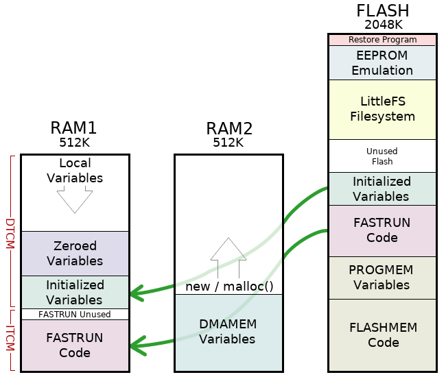
Maybe this diagram & the info on the product page, which Defragster mentioned in msg #2, can help you to understand the memory layout.
- Status
- Not open for further replies.