lolahandycam
New member
Hi All,
I know there is a thread similar to this one but i could not fix my issue with it :/
I'm currently building a sequencer for my modular synthesizer following ExtraLife videos (for Arduino UNO) : https://www.youtube.com/watch?v=Zm5zT1KV26I&list=PLXcIAQij6ZZKMTHAFv8BHvEnsouNYhx3t&index=3
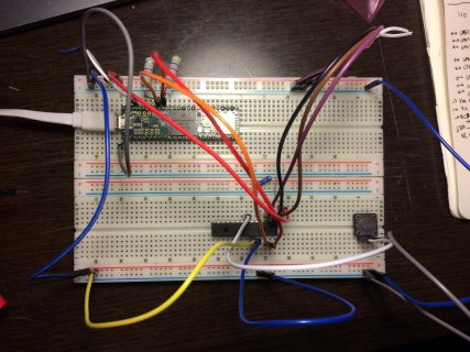
I'm trying to use the MCP23017 with the Teensy 3.6 to be able to acces button input and control LED.
To dive into this, i downloaded the Adafruit_MCP23017 library and tried the first example.
This example is for the Arduino UNO, in order to make it work with the teensy, i feed the MCP23017 with 3.3V instead of 5V and i added two 4.7k ohms pullup resistors between SCL0 (Pin 19) and SDA0(Pin 18).
The rest remain exactly the same.
Nothing happens to the pin13 LED when i press the button.
I have tripple checked my wiring, im pretty sure there is something simple that i did not get but i could find it on my own
Below photos of the breadboard, and wiring "diagram"
and code of the Example "button" in Adafruit_MCP23017.h library
Thank you in advance for your attention <3
Alix
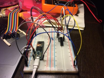
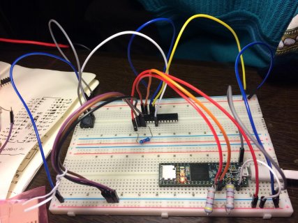
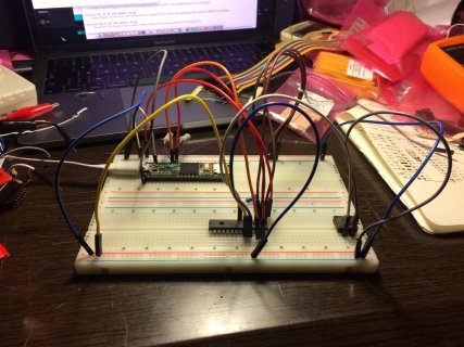
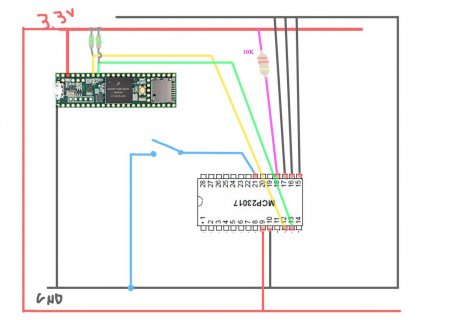


Code:
#include <Wire.h>
#include "Adafruit_MCP23017.h"

// Basic pin reading and pullup test for the MCP23017 I/O expander
// public domain!

// Connect pin #12 of the expander to Analog 5 (i2c clock)
// Connect pin #13 of the expander to Analog 4 (i2c data)
// Connect pins #15, 16 and 17 of the expander to ground (address selection)
// Connect pin #9 of the expander to 5V (power)
// Connect pin #10 of the expander to ground (common ground)
// Connect pin #18 through a ~10kohm resistor to 5V (reset pin, active low)

// Input #0 is on pin 21 so connect a button or switch from there to ground

Adafruit_MCP23017 mcp;

void setup() {
  mcp.begin();      // use default address 0

  mcp.pinMode(0, INPUT);
  mcp.pullUp(0, HIGH);  // turn on a 100K pullup internally

  pinMode(13, OUTPUT);  // use the p13 LED as debugging
}


void loop() {
  // The LED will 'echo' the button
  digitalWrite(13, mcp.digitalRead(0));
}
