Multiplexing rotary encoders or using port expander. What will work with the library?

Here's where it's at.

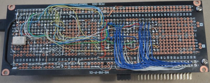
DSC_0836.jpgDSC_0837.jpg


Relevant circuitry has CLK and LOAD buffered with 74HCT245, 74HC165's @ +5v and 470R/910R voltage divider between SERA and SERB and respective T3.2 pins. A 34way ribbon cable ~ 20 Cm long connects the two boards
Using the 74165 example, all 16 encoders work beautifully. I like the way the library deals with setLimits etc. and currently experimenting with 0-127 in most cases for Midi purposes.

Experimented with 2R/1C debounce (Bourns) circuit which was counterproductive as the HC165 thresholds did not like it, so reduced the bottom R which got it working but made absolutely no difference to readings. No debounce was addded.

Looked into the Callbacks example and all 16 encoders work there. Interestingly, (CountMode::full) and setLimits(0,16), when you tweak an encoder past a limit, jumpy values are still emitted. I sniffed in delay.h and fiddled which seemed to subdue some jumpiness even with silly numbers.

Am aware that the 74HCT245 will introduce some propagation delay but used it as am thinking of playing with at least another 16 encoders (not on this build) and maybe double that again so am figuring some help to drive CLK and LD might be a good idea.
 
Congratulations, looks cool indeed. Here a few remarks:

...
74HC165's @ +5v and 470R/910R voltage divider between SERA and SERB and respective T3.2 pins.

The T3.2 is 5V tolerant by design. So, the voltage divider to get the 5V input down to 2.6V is not really needed. (But won't hurt of course).


Using the 74165 example, all 16 encoders work beautifully
Glad to hear that. I never tried more than 8.

I like the way the library deals with setLimits etc. and currently experimenting with 0-127 in most cases for Midi purposes.
I added range limiting (hard and cyclic) after I realized that this is surprisingly complex if a user only has the counter values. It is trivial however from within the library where you have the count up / down events directly.

Experimented with 2R/1C debounce (Bourns) circuit which was counterproductive as the HC165 thresholds did not like it, so reduced the bottom R which got it working but made absolutely no difference to readings. No debounce was addded.
Generally, there is absolutely no need for debounce electronics for the half / and quarter count modes. The implemented state machines can always distinguish between a bounce pulse and a count pulse.
Here the state machine I use for the quarter countMode. The circles are the states, arrows denote state transitions, the numbers are the A/B signals. State A(0,0) is the state at the mechanical detent.
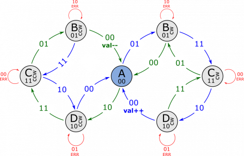
statemachine_quarter.png

Bouncing can only happen between two neighboring states (only one switch is operated at a time in quadrature encoders). As you can see, the count up/down events (val++/val--) have no chance to be triggered by bouncing. You 'pay' for that by having only a quarter of the possible counts per revolution. But this usually is no problem since this corresponds to the mechanical detents. Actually, they don't place the detents at every possible edge of the encoder to allow such algorithms to eliminate bouncing without additional (expensive) parts.

When I find some time I'll add an explanation of the used algorithms to the library documentation.

Looked into the Callbacks example and all 16 encoders work there. Interestingly, (CountMode::full) and setLimits(0,16), when you tweak an encoder past a limit, jumpy values are still emitted. I sniffed in delay.h and fiddled which seemed to subdue some jumpiness even with silly numbers.

I'm afraid, this is to be expected. In 'full' count mode the algorithm counts each edge of the quadrature signal. This is usually done for bounce free optical/mechanical encoders only. Also, it wouldn't make sense for mechanical encoders with detents since at each detent you'd get increments of 4 (or 2 for x2 encoders).
In full mode the quadrature algorithm will ensure that after the bouncing period the counter will be at the right position but while the switches bounce the counter will go up/down on each and every bounce. The polling algorithm will reduce the pain a bit since it doesn't see all edges. Interrupt based algorithms can give you hundreds of up/down events during bouncing. For setpoint applications this is normally not a big deal, for menu selection applications you might get weird effects.

If you limit the count range you normally get no events/callbacks if the encoder is turned above the limit. But since you are using full mode the counter will see rapid up/down events during bouncing and will trigger corresponding callbacks. You can fix this by using quarter or half count mode but this will reduce your resolution by 4 or 2 respectively. If this is not acceptable you might try your hardware debouncing again. In this case it might actually improve the behaviour.
Please also note that you can choose the count mode per encoder. So you could use the quarter mode for encoders where necessary and use the full mode for the others. Here a quick example showing this. Setting encoder 4 to half eliminates the spurious callbacks at the limits.

Code:
#include "Arduino.h"
#include "EncoderTool.h"
using namespace EncoderTool;

constexpr unsigned encoderCount = 8; // number of attached  (daisy chain shift registers for more than 8)

constexpr unsigned QH_A   = 0; //output pin QH of shift register B
constexpr unsigned QH_B   = 1; //output pin QH of shift register A
constexpr unsigned pinLD  = 3; //load pin for all shift registers)
constexpr unsigned pinCLK = 4; //clock pin for all shift registers
                               //74165 datasheet: http://www.ti.com/product/SN74HC165

EncPlex74165 encoders(encoderCount, pinLD, pinCLK, QH_A, QH_B);

void setup()
{
    encoders.begin([](int i, int v, int) { Serial.printf("%d: %d\n", i, v); }, CountMode::full);
    encoders[4].setCountMode(CountMode::half);
    encoders[4].setLimits(0, 16);
}

void loop()
{
    encoders.tick();
}

Am aware that the 74HCT245 will introduce some propagation delay but used it as am thinking of playing with at least another 16 encoders (not on this build) and maybe double that again so am figuring some help to drive CLK and LD might be a good idea.

I can't imagine that the small propagation delay of the '245 will do any harm. However, the whole thing is limited by the duration of the readout of all encoders. If we assume that reading out will take some 5µs per encoder you'll end up with a time of 160µs for 32 encoders. Thus, if the Teensy does nothing else than reading out the encoders it can only do that a frequency of 1/160µs = 6.3kHz which might get borderline for your encoders. However, the readout algorithm is not really optimized at the moment (using delayMicroseconds(1) for wait times where 150ns should be sufficient). Optimizing this should get you some additional headroom. A T4 might be a better solution then (and since you have your voltage dividers you should be able to replace it without hardware change...)
 
Wow, thank you @luni for your in-depth reply, a little over my head not having learned any of this stuff in class or whatever, but I get the drift that my nose took me to a non-option with callbacks.

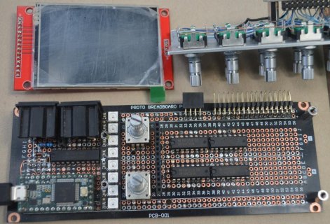
The current build is a kind of Teensy Midi development kit and the soldering iron has had some time off while I've done some more mechanical edits.

Not adding more encoders to this build and the level-shift strategy I've used was crafted mindful of a future T4 based project. Would like to add one more 74165 for some buttons but have yet to dig into the library to see if that option exists. Otherwise, the two encoders on the mainboard are now redundant and are to be replaced with two pots which liberates enough pins.

Have made a baseplate and added board real-estate for some I2C goodies so is time to warm up the soldering iron again.

Thank you for the the work you did in that last post and will endeavor to digest the content.

Cheers for now.
 
Would like to add one more 74165 for some buttons but have yet to dig into the library to see if that option exists.

Added support for encoder buttons in v2.1.0. They are debounced by the Bounce2 library. Unfortunately the Bounce2 library included in Teensyduino is a bit outdated. You need to install the latest Bounce2 (>=2.53) via the library manager to get it working. The buttons work with all polled encoders. I.e. the multiplexed encoders and the PolledEncoder class. I didn't implement button support for the interrupt based Encoder class since that would make debouncing difficult. If you are using the interrupt based encoder it is best to handle the buttons manually with Bounce2

Here a usage example for the PolledEncoder class also showing the use of the new valueChanged and buttonChanged functions:

Code:
using namespace EncoderTool;

PolledEncoder enc;

void setup()
{
    constexpr int pinA = 0, pinB = 1, pinBtn = 2;
    enc.begin(pinA, pinB, pinBtn);
}

void loop()
{
    enc.tick();

    if (enc.valueChanged())  { Serial.printf("value:  %d\n", enc.getValue()); }
    if (enc.buttonChanged()) { Serial.printf("button: %s\n", enc.getButton() == LOW ? "pressed" : "released"); }
}

And here an example using the 74165 multiplexer and displaying button state and encoder value with callbacks:

Code:
#include "EncoderTool.h"
using namespace EncoderTool;

constexpr unsigned encoderCount = 8; // number of attached encoders  (daisy chain shift regesters for more than 8)

constexpr unsigned QH_A = 0;   //output pin QH of shift register B
constexpr unsigned QH_B = 1;   //output pin QH of shift register A
constexpr unsigned QH_C = 2;   //output pin QH of shift register C (buttons, optional)
constexpr unsigned pinLD = 3;  //load pin for all shift registers)
constexpr unsigned pinCLK = 4; //clock pin for all shift registers
                               //74165 datasheet: http://www.ti.com/product/SN74HC165

EncPlex74165 encoders(encoderCount, pinLD, pinCLK, QH_A, QH_B, QH_C);

void buttonChanged(int state)
{
   Serial.printf("button: %s\n", state == LOW ? "pressed" : "released");
}

void anyValueChanged(int idx, int value, int delta)
{
    Serial.printf("Enc_%d: value: %d delta:%d\n", idx, value, delta);
}

void setup()
{
    encoders.begin(CountMode::quarterInv);

    // Attach callback invoked when any encoder value
    encoders.attachCallback(anyValueChanged);

    // setup encoder[0] for limited count rate and a button callback
    encoders[0].setLimits(0, 10);
    encoders[0].attachButtonCallback(buttonChanged);

}

void loop()
{
    encoders.tick();
}
 
Awesome!

Causes a re-think. Have exactly enough holes so will hook up all encoder buttons. Ran out of 165s.

Have you considered using a 74595 and 74138 to generate S0-S3 and E for the 4067 version which offers easy expandability without further increasing MCU pin count? SIGs are bussed onto a single MCU pin.
 
Have you considered using a 74595 and 74138 to generate S0-S3 and E for the 4067 version which offers easy expandability without further increasing MCU pin count? SIGs are bussed onto a single MCU pin.

Actually, to expand the 4067 based solution to 32 encoders you only need an additional inverter (or transistor) to get a 5th address line (S4). you can directly connect the outputs of the 4067 without additional logic. From the library point of view the loop clocking in the encoder signals needs to be extended from 16 to 32 loops. That should be all. So, this would be quite trivial. If you extend that to even more encoders you will ultimately run into timing problems as shown above. The 4067 gets significantly faster when you power it with 15V. If you keep the encoder pullups at 3V3 you should be safe with the input voltage to the Teensy.
 
Ok, thanks.
To to clarify, query re:-138 and 4067 relates to a fairly imminent upgrade (Mega to T3x) on an earlier Midi controller project currently using 14 pots and 48 H/W debounced buttons via 3x 4067. Have used 138 here. The pots are a pain and the device badly needs more MCU horsepower so am forward thinking EncoderTool and looking at grafting a Teensy.

Just like cluttered desk, many thoughts simmer in mental melting pot.

Have just given the current build a workout and am very happy with the results, many thanks for creating Encoder Tool.

Next to get 8 - 15 onscreen while awaiting more bits and pieces..
 
Hi Luni,
Thank you for creating Encoder Tool. That's exactly what I was looking for in order to multiplex 6 encoders for my projects with HC165 shift registers.
However I tried to test the library and it looks like there is a problem compiling it with Teensyduino.
I got the following issue
Code:
/Users/pro/Documents/Arduino/libraries/EncoderTool-master/src/EncoderButton.h:19:14: error: 'bool EncoderTool::EncoderButton::readCurrentState()' marked 'override', but does not override
         bool readCurrentState() override { return curState; }
              ^
Erreur de compilation pour la carte Teensy 4.0
Do you know what could be wrong ?
Thank you in advance.
Best regards
 
Yes, you are using an outdated version of Bounce2.
You can fix this by installing a current version of Bounce2 (Library manager, or download directly from GitHub). Alternatively, you can install the current Teensyduino beta version. It ships with a new Bounce2.
 
Yes you were right, I updated Bounce2 and it works just well, thank you.
Now I'm trying to use your library to make what I want. I took a look at your documentation and read the library but because I'm not an advanced programmer like you seem to be, I have difficulties to "tune" the operating of your example 02_Multiplexed_74165.

* 1st
I wired my 6 encoders from A to F HC74165 inputs.
They appear in serial monitor from E7 to E2 (the first one that I would like to be E0 appear at E7 and the last one I would like to be E5 appear at E2).
If I understand well, it's because in your code you consider H input to be the first input ?
So what would you suggest, rewire the encoders or modify the code ?

*2nd
It looks like there is no speed or acceleration management in your code. In effect, I want to use encoders for a MIDI controller and this kind of function is very convenient to go to min and max values more quickly.

*3rd
I would like to use built-in encoders push button.
So I added an extra 74165 shift register. But I can't figure out how to configure it with "EncPlex74165 encoders" class and how to get buttons values.

Thank you in advance for your help and bravo for your work.
Best regards,
 
Now I'm trying to use your library to make what I want.
Sounds like a good plan :)

* 1st
I wired my 6 encoders from A to F HC74165 inputs.
They appear in serial monitor from E7 to E2 (the first one that I would like to be E0 appear at E7 and the last one I would like to be E5 appear at E2).
If I understand well, it's because in your code you consider H input to be the first input ?
So what would you suggest, rewire the encoders or modify the code ?

As you observed correctly, the first encoder in the array is the first which is clocked in. I.e. the one connected to the "H" pins. The example just prints out the encoder values by increasing the array index from 0 to the number of attached encoders. If you want to display them in the other direction you can simply change the for-loop to run backwards:

Code:
for (unsigned i = encoderCount-1; i >= 0; i--)   // <-  loop backwards...
{
    Serial.printf("E%u:%3d ", i, encoders[i].read());
}


*2nd
It looks like there is no speed or acceleration management in your code. In effect, I want to use encoders for a MIDI controller and this kind of function is very convenient to go to min and max values more quickly.
No, there isn't. But you can always do the calculation using the position values you get from the library I assume.

*3rd
I would like to use built-in encoders push button.
So I added an extra 74165 shift register. But I can't figure out how to configure it with "EncPlex74165 encoders" class and how to get buttons values.

I assume you are using a setup similar to the one shown in the extras folder:
Schematic_part.jpg


You would then do something like the code shown below:
The code shows how to check for button changes and how to attach a callback which will be invoked if a button changes. It also shows how to define some encoder references to make the code easier to read:

Code:
#include "EncoderTool.h"
using namespace EncoderTool;

constexpr unsigned encoderCount = 8; // number of attached  (daisy chain shift regesters for more than 8)

constexpr unsigned QH_A = 0;   //output pin QH of shift register B
constexpr unsigned QH_B = 1;   //output pin QH of shift register A
constexpr unsigned QH_S = 2;   //output pin QH of shift register ENC_S (buttons)  //<====  Add pin definition for the third shift register
constexpr unsigned pinLD = 3;  //load pin for all shift registers)
constexpr unsigned pinCLK = 4; //clock pin for all shift registers

EncPlex74165 encoders(encoderCount, pinLD, pinCLK, QH_A, QH_B, QH_S); // <====Add the "button register pin" QH_s to the constructor)

auto& volumneEnc = encoders[0]; // define some references for cleaner code
auto& balanceEnc = encoders[7];
auto& menuEnc = encoders[3];

// simple callback
void MenuButtonPressed(int32_t btnState)
{
    Serial.print("Menu button: ");
    Serial.print(btnState); // HIGH / LOW
    Serial.print(" ");
    Serial.println(menuEnc.getValue()); // current encoder value
}

void setup()
{
    // You can use a callback or poll in loop to get the button presses

    menuEnc.attachButtonCallback(MenuButtonPressed); // invoke MenuButtonPressed when button changed
}

void loop()
{
    encoders.tick();

    if (volumneEnc.buttonChanged())
    {
        Serial.print("Volume button: ");
        Serial.print(volumneEnc.getValue()); // HIGH / LOW
        Serial.print(" ");
        Serial.println(volumneEnc.getValue()); // current encoder value
    }
}
 
Ok, got the buttons values and I will think about a function to handle acceleration, thank you.

I'm still struggling with my first problem I.e the encoders wiring, reading and parsing.
If you want to display them in the other direction you can simply change the for-loop to run backwards:
You're right I could just sort and rename encoders in serial monitor. But when I put 6 as encoderCount, I feel like my first two encoders (wired at A and B 74165s inputs) will be ignored whatever I do in serial. Am i right ?
 
You're right I could just sort and rename encoders in serial monitor. But when I put 6 as encoderCount, I feel like my first two encoders (wired at A and B 74165s inputs) will be ignored whatever I do in serial. Am i right ?

That's true, if you set the encoder count to 6 it will clock in only 6 encoders. If you connected two of them at the other end they would not be read. If you don't want to change your wiring you can always clock in 8 encoders and simply ignore the first two.

Ok, got the buttons values and I will think about a function to handle acceleration, thank you.

Thinking of it, it might be the easiest to use a callback for this. Something like this should work in principle but needs to be fully worked out of course:

Code:
uint32_t lastTime = 0; 

void accelerationCB(int curPos, int delta )  // curPos is the current encoder position, delta is the difference to the last position (usually +1 or -1)
{
    uint32_t now = micros();          // get current time
    float dt = now - lastTime;         // time difference    
    float velocity = delta / dt;          

    // calculate some "virtual" count value from 'curPos' and 'velocity' and store it somewhere (not in the encoder)

    lastTime = now;  // book keeping
}

void setup()
{
    encoders[0].attachCallback(accelerationCB); // invoke when encoder value changed
}
 
Hello Luni

I’m working with sacreYoubeurt on a project of MIDI controler. Thanks for your work on the library EncoderTool.
We were trying to use this library on a under-file called by a C++ file and by our principal program but it doesn’t work.
Here is what the compiler told us*:
«*D:\Arduino\libraries\EncoderTool-master\src/Single/Encoder.h:47: multiple definition of `EncoderTool::Encoder::~Encoder()'
D:\TEMP\arduino_build_457262\sketch\TEST_BUG.ino.cpp.o:D:\Arduino\libraries\EncoderTool-master\src/Single/Encoder.h:47: first defined here»

I join you a simple sketch called «*TEST_BUG*» that shows the error described above.

With the help of my father, better in C++ than me, we have seen that this is the definition of the destructor ~Encoder, placed in Single>Encoder.h, that probably causes the issue. So we have changed a little bit the library*: we have created an other file in .cpp that contains only this definition*:

Code:
#include "Encoder.h"

namespace EncoderTool {
    Encoder::~Encoder()
    {
        detachInterrupt(pinA);
        detachInterrupt(pinB);
    }
}
and we have removed the destructor definition in the file Encoder.h.
It solves this issue, and make our sketch work well, but I don’t know if it can bring other problems.

I hope this post is understandable, because I probably don’t have the exact vocabulary, but I wanted to inform you about that. Maybe we don’t use the library as we should, or maybe there is another way to solve this issue. Please tell me what you think about this.

Thank you in advance,
Best regards


View attachment TEST_BUG.zip
 
There was an "inline" missing in the destructor declaration. I uploaded a fix to GitHub. Can you try if the current version works for you? And, thanks for spotting yet another bug....

BTW:
The fix you did is the correct way to do this. Often I'm lazily writing code directly in the header but this needs an inline declaration of course to inform the linker not to get confused about multiple definitions if you include the header from more than one translation unit.
 
Last edited:
Hey, sorry for digging out that old thread. I am currently working with 19 Encoders on 2 I2C devices and while it is useable, it starts to fail when you turn the Encoders too fast.
As I am working on a second version of the PCB currently, I thought about redoing that Encoder thing. First I stumbled upon Absolute Encoders, but they seem to be hard to get and expensive, so working with 74HC165 might be a possible solution.
Before I build a test setup, buy components, I would like to understand how much time this solution takes up. If I understand the code correctly, thats per update:

150ns waittime for the shift registers to read their value
+ 100ns for n-1 encoders to read
+ the time the CPU takes for executing all the code.

thats 2µs + the time for the code.
Putting that on a 500µs Interval would be fine to run "in background".

But there is a post stating it is 5µs per Encoder (a totally different beast). Is that, because it was done with a very early version of the library?

Thanks in advance for an answer!
 
Yeah, I did. It is waiting one microsecond per encoder for the adress change to be executed. As there are only 16 possible per device, we are talking 16micros instead of 2.
 
Back
Top