So for the last 4 months I've been developing what I call a plug and play engine management system for a very popular off-road vehicle. This system basically adapts an aftermarket engine control module to the vehicles oem connectors and keeps all the functions working like they did from the factory while allowing full control over the engine fuel, ignition maps, etc. I use the Teensy to emulate the cars original can-bus messages. All that works great. I have a couple issues and concerns that i'm hoping someone with more experience can help meh with.
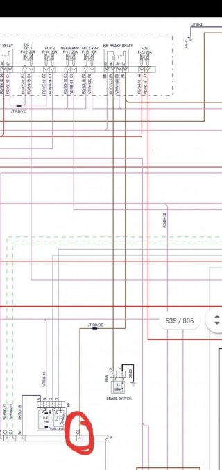
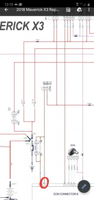
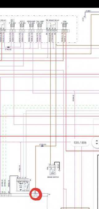
At all times the teensy monitors the "start/stop" button and the brake switch button. Both are switched 12v signals. Both signals are also taken from the positive side of a relay. The problems i'm having I also had with an arduino variant of my design. Sometimes when the brake pedal is pressed it will also set the start button signal high even though the button isn't being pressed?.. They are both on separate pins with voltage dividers and both zener and tvs diodes for protection. Since the box also controls the main ignition relay it can cause the car to shut off while braking.
I have masked this with code by not reading the input if the other is high. Also be taking the readings only every 20mS or so.
I don't know if the relay back emf spikes are causing this or what.. Im kind of stuck..
Some engineers say use a opto-couple. But I've read those have reliability problems.
I would like to use a schmitt trigger but Im afraid the output wont go high while cranking because the voltage can drop below 6v and after the voltage divider the input voltage might be too low..
I did notice that my inputs are really close the high level input threshold.. But That's hard to get around because the wide voltage range my conditioning circuit has to work with about 5v-15v...
any input is greatly appreciated. I attached images of the cars brake and start input circuits.