As I understand it, any of the TMC drivers that can run on 3.3V or 5V are affected by it. PFET is not a bad idea at all. I've been through a lot of TMC driver datasheets (2208, 2209, 2130, 5160) and did not see anything on the timing of VCC_IO vs VMot. Watterott has
some info here. Though I'm not 100% sure what he is trying to say on
this page.
Looks like they are clamping VCCIO to ground until VM is present. Could be nasty to some power supplies. I like my p-fet switch much better. Especially considering I'm also turning on the VS motor supply via an IO line from the Teensy. I also read lots of TMC docs and never saw anything on it so that was why I asked. Now that I'm warned, one IO pin, and <$1 in parts fixes the VCCIO issue.
My power supply turn on sequence 56V POE comes up. 5VDC Vin for Teensy is generated from it. Teensy powers up and generated it's 3.3VDC supply. During Teensy initialization, POE power mode allowed is negotiated. Could be via hardware or network packets. Once negotiated the dummy hardware loads are turned off, and the VS motor supply is turned on. After it is stable, then the VCC_IO p-fet can be turned on. In the future I may switch to higher voltage stepper motor driver circuits so I can directly use the POE power to run the stepper motors. Likely at the same time I switch from 2-phase steppers to switched reluctance ones.
I don't have specific back EMF protection. I do have MOVs as part of my EMI filter. Clamping the motor lines to be between GND-diode drop and VS+diode drop would be good for robustness.
As for digital isolation for the rest of the lines. Yes, capacitive and RF digital isolators are faster and have less glitches. Opto could be used if Schmidt triggers are used on the outputs, but that adds cost and PCB space. Something like the TI TXS0102 or ON NTS0102-Q100 like I've used in the past would work, widely second sourced. Now I'd use the flip chip 8 pin BGA package and reflow them. In the past I used the SO-8 and hand soldered. The 8 pin BGAs being two rows of 4 .25mm ball pads spaced on .5mm centers meets my .20 minimum spacing requirements for low cost 2oz copper PCBs.
Yeah, I surveyed a bunch of PCB manufacturers for low cost 4 layer 2oz copper on all 4 layers. To be able to sent to any of the lowest cost ones I needed >= 0.15mm copper to copper spacings and trace widths. So my PCB has been designed with that in mind. I actually set my minimum to 0.2mm for higher reliability, why push it. The extra copper will give great heat sinking in the PCB for fanless operation even at a full 2A load. I'm not sure what my home made stepper motors will need. They are pieces of art, not traditional stepper motors.
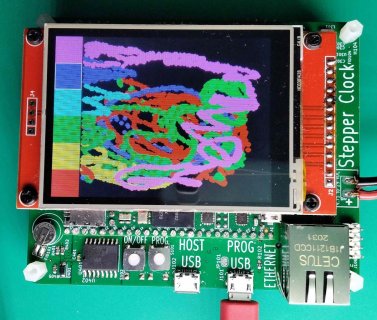
Pic 1 is what I'm testing and writing code to now. Still working despite the VCC_IO being hooked directly to the Teensy 3.3VDC. Unfortunately I don't have a pic from before I added the TFT display. All circuits worked with test code. It just has a regular ethernet connection and a separate 9 to 29VDC motor power supply. In this one I'm using the TFT touch screen. Next one will use an OLED display with 4 keys for setting parameters. Ethernet is for getting the current time from the internet.
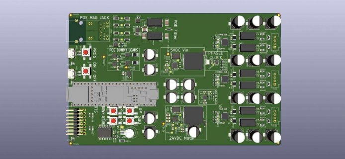
Pic 2 is a 3D model of the latest proto PCB layout. I haven't put digital isolators in yet. This does have resistors on the IO lines to the TMC stepper motor drivers. I also need to swap around pin use, and finish routing it. This one has the stepper motors off one end of the Teensy, not along one side like the current proto I'm testing now. That changes the best pin selection around some. Proper #defines and #ifdefs in the software makes it easy to have multiple different boards using the same code base. POE power and IO are on one end, and the stepper motor connects are on the other. It will slip into a standard 160mm by 100mm Eurocard slot.