Senior design project UIUC

Status
Not open for further replies.
A 741 will need +/- supplies of > 5v to deliver anything like the voltages required. They don't drive inputs anywhere near the rail voltages.

Try an LM358 series OpAmp, which works well in single supply mode at low voltages. They are cheap, plentiful and come in a range of packages.
 
A 741 will need +/- supplies of > 5v to deliver anything like the voltages required. They don't drive inputs anywhere near the rail voltages.

Try an LM358 series OpAmp, which works well in single supply mode at low voltages. They are cheap, plentiful and come in a range of packages.

When you say single supply mode, do you mean that V+ is a positive voltage and V- is GND?
 
So the LM358P's are working for the biasing circuit. Still needs to be dialed in just right but I can tell it will work. Phew! Looks like N-order filters will be needed as well. The tweets and mids still trigger the bass light strip on a 1st order LPF. I think we have made a lot of progress. We need to start making our presentation and writing the final report soon, so not much time left for circuit work.
 
Good to hear that the basics are working well, and you're now tweaking!

I'm surprised that the tweets are triggering the bass channel. You should have nearly two decades of frequency between them (i.e. nearly 20 dB cut, with a single pole filter). How level sensitive is the issue?

While adding more poles is the better way to solve the problem, moving the poles (component values) of the filters you already have further away from the neighboring channels might also help a bit.

You could move the pole of the bass channel LPF down quite low. If you use 30 Hz, you'll still have reasonable levels at 100 Hz, and -10dB @ 300 Hz.

It sounds, overall, that the project is delivering exactly what the instructor is likely to be intending:

  • Hands-on learning with some of the basic electronic building blocks.
  • Building a team approach to problem solving and solution refinement.

Happy days!
 
So it seems that running audio through the lm358 adds some static/crackling type noise. I did some searching online and found that there are audio opamps. Have you ever used a opa1671?
 
yes, but they're not required for this application.

Audio opamps are used for very low noise (hiss) / low distortion, neither of which match your description of static/ crackling.

those are most often associated with volume pots with DC across them ( no AC coupling between stages) or poor joints, loose sockets, etc.

the other possibility is overdriving the ADC, this will cause a sound like crackling.

check your wiring and other connections first, and make sure you're well-within the allowed input range of the ADC.
 
That makes sense. However, the ADC wasn't even connected. I isolated this circuit http://www.falstad.com/circuit/circuitjs.html?cct=$+1+0.000005+0.20306040966347483+50+5+50%0A409+352+240+416+240+1+0.6+4.1271460785371215+0.0231+0%0AR+384+272+384+304+0+0+40+5+0+0+0.5%0Ag+384+208+384+192+0%0Aw+416+240+528+240+0%0Aw+416+240+416+160+0%0Aw+416+160+320+160+0%0Aw+320+160+320+224+0%0Aw+320+224+352+224+0%0Aw+352+256+320+256+0%0Ac+320+256+320+304+0+0.00001+0%0Ag+320+304+320+320+0%0Ar+320+256+256+256+0+1000%0AR+256+256+208+256+0+1+800+1.6+0+0+0.5%0A all by itself and took the output into some speakers.

So the popping is coming from something in that circuit. I read online that adding a resistor to GND on the output can help, but I added a 100 ohm and it didn't help.

Also the input was a song from my phone that works in other similar passive setups so I know the input couldn't be the issue. Finally, the speakers aren't the issue because those work as well in passive filtering setups.

Those are just the values that the resistor and cap defaulted to in the program. I don't remember the values we used. I think it was 82 ohm and 10uF
 
OK, I'm not sure which "output" you're referring to.

If it's from the Teensy DAC , then you'll need to offset the value output, so quiet (sample == 0) is equal to half the maximum output value, AND put a series capacitor (10uF or so) between it and the speaker to stop the DC.

OK, that circuit on Falstad doesn't make sense for what you're doing. It is a Low Pass filter with a basic gain of 1. The Low Pass pole is at 16 Hz. Maybe it's intended as a subwoofer driver?

Your added resistor (100 ohms to ground) should be irrelevant - as I beleive you already have the speaker connected across it (say 8 ohms).

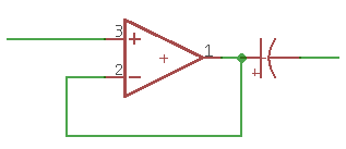
A more normal buffer would look like this (assuming single supply operation and DAC output).

op.png
 
Yes the circuit linked in post #33 has nothing to do with our project. It was just to test that the opamp can have a clean output (meaning the output of the opamp).

As it turns out, when i switch the inverting and non-inverting inputs, the opamp works. these are the ones i bought https://www.amazon.com/BOJACK-LM358P-Operational-Amplifier-LM358N/dp/B07WQWPLSP/ref=sr_1_1_sspa?dchild=1&keywords=lm358p&qid=1587308390&sr=8-1-spons&psc=1&spLa=ZW5jcnlwdGVkUXVhbGlmaWVyPUFFTlROVE1WOUZCSTcmZW5jcnlwdGVkSWQ9QTAyMTQzMzkxNU9aVk9DTlNIRlRBJmVuY3J5cHRlZEFkSWQ9QTA4NDY5MzkyTFBBTERMQUQ0QjEwJndpZGdldE5hbWU9c3BfYXRmJmFjdGlvbj1jbGlja1JlZGlyZWN0JmRvTm90TG9nQ2xpY2s9dHJ1ZQ== Kinda weird.

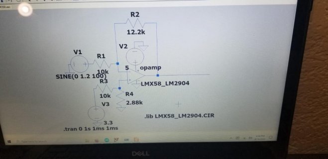
LTSPice simulates it just fine with the 3.3VDC going into the non-inverting input:
WhatsApp Image 2020-04-19 at 10.31.05 AM.jpg

This opamp design was taken from herehttps://en.wikipedia.org/wiki/Operational_amplifier_applications#Amplifiers

However it seems we placed too much confidence in LTSPice simulations because now when I plug in the resistor values in the Vout equation on that wiki page...well....uh.....I get a negative voltage value for Vout.

So in the end this is my fault for not following through with proper calculations....
 
Not surprising you get a negative output with the + input biased to 3.3 * 2.88/12.88 V and the - input coming from a ground-referenced source!

Try this:
- bias the + input to half the rail voltage.
- add an electrolytic capacitor to the - input. This can be omitted if the 'no output' level of the DAC (this will generally be approximately 1/2 VA, to allow for + & - values of the signal) is the same as the + input's bias voltage.
- add an electrolytic capacitor to the output if you are going to drive a real load.
 
After filtering and then biasing the signals, we basically have the majority of the hardware part of the project complete. However, the higher frequencies are still present in the bass signal. The bass isn't really present in the tweet signal though. We have tried up to an 8th order RC LPF and it still doesn't work the way that we need it to.

I am currently exploring the idea of:

NOT splitting the audio signal into 3 bass, mid, and tweet signals.

Using a LPF with Fc = 5000HZ (open to tweaking) These are the freq values that we pay attention to in terms of translating audio to a visual LED representation.

Sending that into a biasing circuit to bring the signal between 0.2 and 3.1 V

Sending that into A0 and doing a 1024 FFT.

Using that data to translate into an LED array for bass, mid, and tweet.

This will drastically reduce the complexity of our PCB, however I think keeping the one filter, and the biasing circuit will allow us to still get full difficulty points for our PCB.

Our final demo is 9am on Monday.....
 
Code:
#include <Audio.h>
#include <Wire.h>
#include <SPI.h>
#include <SD.h>
#include <SerialFlash.h>

#include <FastLED.h>

#define LED_TYPE WS2812B
#define COLOR_ORDER BGR
#define NUM_LEDS 296
#define DATA_PIN 10
CRGB leds[NUM_LEDS];


#define BRIGHTNESS 40
#define FRAMES_PER_SECOND 120


uint8_t hue = 15;

//uint8_t level[144];
uint8_t oldLevel[144];
uint8_t value[144];
float rawValue[144];


float scale  = 500.0;
float level[16];
int shown[16];

// GUItool: begin automatically generated code
AudioInputAnalog         adc1(A0);           //xy=179,182
AudioAnalyzeFFT1024      fft1024_1;      //xy=401,185
AudioConnection         patchCord1(adc1, fft1024_1);
// GUItool: end automatically generated code

void setup() {
  //IOMUXC_SW_PAD_CTL_PAD_GPIO_AD_B1_02 &= ~ (1<<12) ; // disable keeper
  AudioMemory(12);
  fft1024_1.windowFunction(AudioWindowHanning1024);
  delay(100);
  FastLED.addLeds<1, WS2812B, 10, GRB>(leds, NUM_LEDS);
  FastLED.setBrightness(BRIGHTNESS);
  pinMode(10, OUTPUT);

}


void loop() {

  if(fft1024_1.available()){
    
    level[0] =  fft1024_1.read(0);
    level[1] =  fft1024_1.read(1);
    level[2] =  fft1024_1.read(2, 3);
    level[3] =  fft1024_1.read(4, 6);
    level[4] =  fft1024_1.read(7, 10);
    level[5] =  fft1024_1.read(11, 15);
    level[6] =  fft1024_1.read(16, 22);
    level[7] =  fft1024_1.read(23, 32);
    level[8] =  fft1024_1.read(33, 46);
    level[9] =  fft1024_1.read(47, 66);
    level[10] = fft1024_1.read(67, 93);
    level[11] = fft1024_1.read(94, 131);
    level[12] = fft1024_1.read(132, 184);
    level[13] = fft1024_1.read(185, 257);
    level[14] = fft1024_1.read(258, 359);
    level[15] = fft1024_1.read(360, 511);

    hue = 20;
    for(int i=0; i<16; i++){

      int val = level[i] * scale;

      if(val > 255) val = 255;
      if(val >= shown[i]) {
        shown[i] = val;
      } else {
        if (shown[i] >  6) shown[i] = shown[i] -7;
        val = shown[i];
      }
      if(shown[i] == 0) {
        leds[i] = CRGB::Black;
      } else {
        
        leds[i*3] = CHSV(hue, 255, shown[i]-1);
        leds[(i*3)-1] = CHSV(hue, 255, shown[i]-1);
        leds[(i*3)+1] = CHSV(hue, 255, shown[i]-1);
        hue = hue + 15;
      }
    }
    FastLED.show();
    }     //end FFT-available
}

When trying to compile this code I found online I get this error:

Capture.PNG
 
OK, A change of plan isn't a bad thing if you hit a brick wall!

With that error, which pops up every now and then. Usually, it's a badly written call to the constructor, but your call to
Code:
AudioInputAnalog         adc1(A0);
looks OK. Try the base variant
Code:
AudioInputAnalog         adc1;
, which uses the A2 pin, to see if that produces a different result.

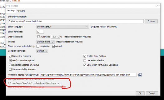
Sometimes it's just pre-built libraries being out of step. The easiest fix is to find your Arduino build directory and delete everything. The build directory is in the top few lines of preferences.txt, which is available from the Arduino Preferences tab.

Annotation 2020-04-27 100512.png

The issue behind this is explained in the design doc for the audio library, if the compiler can't find an update() function for the library object it complains with the vtable error. As you are using inputADC(), which does have an update function,https://www.pjrc.com/teensy/td_libs_AudioNewObjects.html

If you find that FFT responsiveness is a bit slow, you don't need to use a 1024 bucket FFT for this task. The 256 bucket one will be much faster and adequate for B/M/T analysis.

When you do your demo, discuss with your instructor how you got to the final design - it's as important a matter for a team design project as the final outcome.

I be careful mentioning the 8th order filter (just go for 'higher order filters') - as a well-implemented filter of that nature would surely do the job. I'd guess (and so would the instructor) there was something else involved here that allowed HF signals (and maybe not those from your signal source!) to get into the bass. Given the constraints of uni project work, it's OK to not have resolved every issue. Clarifying the issue, understanding the amount of work required to remediate, and prioritising your effort to reach the optimal outcome, are equally important.

Enough of the pep talk.

Well done! It's been a pleasure watching this project evolve and being able to provide some advice along the way.

Richard
 
So it seems a major issue that has gone unnoticed for awhile is our subpar sample rate. We made some adjustments, and now the project is mostly working (Without the FFT). I think that we will do pretty well in the demo tomorrow. We will lose points for not having a PCB, and also for our bass strip not reacting quite as it should. I think overall this was a great project and I learned a lot. All 3 strips lighting up at the same time with different lighting configurations looks super cool!

Thanks Richard!

I'll post a video of the final project later tomorrow.
 
Status
Not open for further replies.
Back
Top