SPI MOSI pulled low too late on Teensy 4.0

Status
Not open for further replies.

geluk

New member
I was having some issues communicating with an ENC28J60 Ethernet controller on Teensy 4.0 using SPI.
At seemingly random intervals, the most significant bit of an octet would get transferred incorrectly, causing the controller to malfunction.

Once I analysed the SPI communication, I noticed that, if the first SI bit is supposed to be a 0, the Teensy pulls SI low on the first rising edge of the clock.
Since I have my SPI configuration set to mode 0 (which is what the Ethernet controller requires), this is too late,
because the ethernet controller will sample SI on the rising edge of the clock - right as it's in the process of switching from high to low.
Because of this, for the same byte, it sometimes reads the first bit as a 0, other times as a 1.

Curiously, this only happens with the most significant bit. All other bits correctly switch state on the falling edge.

I used the following code to reproduce the problem:
Code:
#include <SPI.h>

SPISettings spi0(1000000, MSBFIRST, SPI_MODE0);

void setup()
{
	SPI.begin();
}

void loop()
{
	SPI.beginTransaction(spi0);
	SPI.transfer(0x0D);
	SPI.endTransaction();
	delay(500);
}

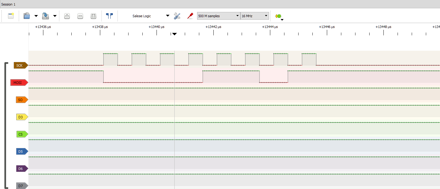
Recording the output of this program with a logic analyser shows this:
As you can see, SI goes low on the first rising edge, but after that, all remaining bits are switched on the falling edge.

4mREJVZ.png


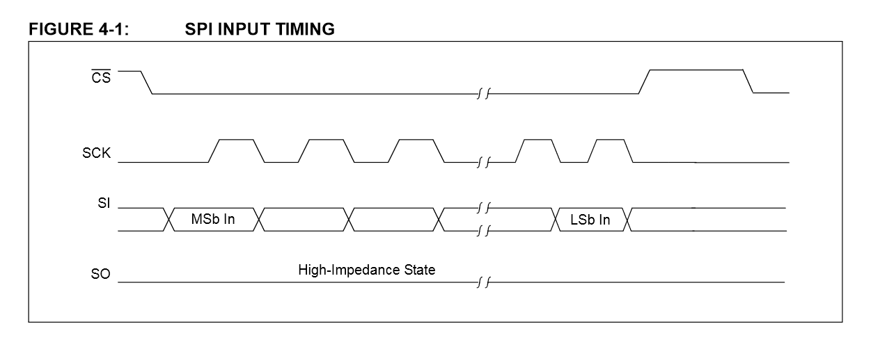
The diagram below is from the ENC28J60 datasheet, which shows that MOSI already needs to be high/low before the first rising edge of the clock passes.


3G8HBA7.png


I am unsure what causes this, and I am wondering whether I am doing something wrong here, if I have bad hardware, or if this is a bug in Teensyduino (I am using Teensyduino 1.51 with Arduino IDE 1.8.12 on Windows).
 
Last edited:
It's definitely an issue with the Teensy 4.0 Hardware or SPI Library. I ran the same code on a Teensy 3.6 at 180MHz with Teensyduino 1.51 and Arduino 1.8.12 and the MOSI signal definitely goes low about half a clock sooner on the T 3.6.

Teensy 3.6 at 180MHz:
T3_6A.jpg

Teensy 4.0 at 600MHz
T4_0A.jpg

I took a quick look at the SPI library code for the T4.0 and tried to match it up with the register descriptions, but nothing jumped out at me that would explain the timing difference. However, my understanding of the behavior of the low-power SPI on the T4.0 is far from complete!
 
I have found that adding some PCS to SCK delay will move the start of SCK to a point after the MOSI signal is stable:

T4_0C.jpg

To accomplish this, you have to edit the source code for SPI.h. To do this you need to copy the SPI library from
C:\arduino-1.8.12\hardware\teensy\avr\libraries folder to your sketch libraries folder. When you do this the library in your sketch folder overrides the original in the Arduino folder.

The text to edit is in the beginTransaction() function for the Teensy 4.0.
Code:
	// Before using SPI.transfer() or asserting chip select pins,
	// this function is used to gain exclusive access to the SPI bus
	// and configure the correct settings.
	void beginTransaction(SPISettings settings) {
		if (interruptMasksUsed) {
			__disable_irq();
			if (interruptMasksUsed & 0x01) {
				interruptSave[0] = NVIC_ICER0 & interruptMask[0];
				NVIC_ICER0 = interruptSave[0];
			}
			if (interruptMasksUsed & 0x02) {
				interruptSave[1] = NVIC_ICER1 & interruptMask[1];
				NVIC_ICER1 = interruptSave[1];
			}
			if (interruptMasksUsed & 0x04) {
				interruptSave[2] = NVIC_ICER2 & interruptMask[2];
				NVIC_ICER2 = interruptSave[2];
			}
			if (interruptMasksUsed & 0x08) {
				interruptSave[3] = NVIC_ICER3 & interruptMask[3];
				NVIC_ICER3 = interruptSave[3];
			}
			if (interruptMasksUsed & 0x10) {
				interruptSave[4] = NVIC_ICER4 & interruptMask[4];
				NVIC_ICER4 = interruptSave[4];
			}
			__enable_irq();
		}
		#ifdef SPI_TRANSACTION_MISMATCH_LED
		if (inTransactionFlag) {
			pinMode(SPI_TRANSACTION_MISMATCH_LED, OUTPUT);
			digitalWrite(SPI_TRANSACTION_MISMATCH_LED, HIGH);
		}
		inTransactionFlag = 1;
		#endif

		//printf("trans\n");
		if (settings.clock() != _clock) {
			static const uint32_t clk_sel[4] = {664615384,  // PLL3 PFD1
						     720000000,  // PLL3 PFD0
						     528000000,  // PLL2
						     396000000}; // PLL2 PFD2				

		    // First save away the new settings..
		    _clock = settings.clock();

			uint32_t cbcmr = CCM_CBCMR;
			uint32_t clkhz = clk_sel[(cbcmr >> 4) & 0x03] / (((cbcmr >> 26 ) & 0x07 ) + 1);  // LPSPI peripheral clock
			
			uint32_t d, div;		
			d = _clock ? clkhz/_clock : clkhz;

			if (d && clkhz/d > _clock) d++;
			if (d > 257) d= 257;  // max div
			if (d > 2) {
				div = d-2;
			} else {
				div =0;
			}
	
		//	_ccr = LPSPI_CCR_SCKDIV(div) | LPSPI_CCR_DBT(div/2);  //original code
		// add some PCS to SCK delay to make sure SCK starts after MOSI is stable
		 	_ccr = LPSPI_CCR_PCSSCK(128)	| LPSPI_CCR_SCKDIV(div) | LPSPI_CCR_DBT(div/2);				
		} 
//		Serial.printf("SPI.beginTransaction CCR:%08X  TCR:%x\n", _ccr, settings.tcr);
		port().CR = 0;

		port().CFGR1 = LPSPI_CFGR1_MASTER ;

		port().CCR = _ccr;
		port().TCR = settings.tcr;
		port().CR = LPSPI_CR_MEN;

	}

I added a large delay of 128 and it delayed SCK about 1/2 cycle. A shorter delay may be effective. How much shorter will depend on the setup time required by your SPI peripheral.

I also found that slowing the T4.0 to 150 MHz moved the SCK edge a bit without editing the source since there is a default delay of 1 clock cycle, and with slower clocks the SCK is delayed 4 times longer.
 
Thank you for your help investigating this! I looked through the T4 SPI library code as well, but with how little I know about the microcontroller, that didn't get me very far.
Nice to see that you may have found a workaround. I'm going to apply your patch to see if I can get it to work.
 
Hi,
Sorry to revive an old thread but mborgerson's solution helped me get the hardware spi working with a BMP388 sensor and I was wondering if there is any "official" solutions and if they are going to be included in any of the future Teensyduino releases?
 
I was having issues with SPI on a Teensy 4 as documented here:
https://forum.pjrc.com/threads/6024...INA-modules-to-support-Teensy-and-more-boards

And it was fixed by using the latest version of the SPI library (which I think includes a similar fix to above) from here:
https://github.com/PaulStoffregen/SPI

I don't think the latest SPI library changes are in an official Teensyduino release, and the whole Teensyduino release/dependency structure seems a bit opaque to me. I can't see any mapping of which library versions are in which Teensyduino releases.
 
Thanks dav1d, can confirm that this works too, I guess this will get into one of the future releases at some point so I'll just keep updating it manually for now.
 
Status
Not open for further replies.
Back
Top