Teensy 4.0 hardware / schematic question

Status
Not open for further replies.

ilium007

Well-known member
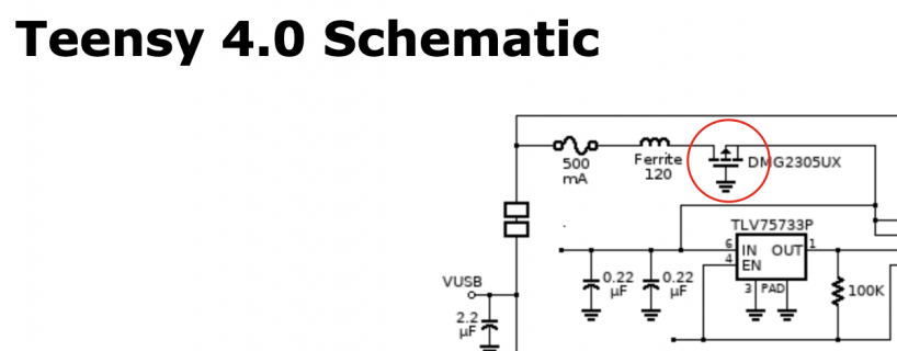
Hi - can someone please tell em the purpose of the P-channel MOSFET shown below? To me it looks as though the gate is permanently tied to GND which would mean the MOSFET is always allowing current to flow through the source-drain channel to supply the 3.3v regulator. Why is this MOSFET required at all?
Screen Shot 2020-03-09 at 11.36.02 am.png

Second question, does anyone know the part number for the momentary push button switch used on the Teensy 4.0? Is it the PTS810? https://au.mouser.com/Search/Refine?Keyword=pts810
 
this question came up and was answered yesterday.

IIRC in this mode as noted in that post - it acts as a simple diode with a lower voltage drop that a diode would.

Paul has listed the button part before on forum - not sure if it might be in any OSH board BOM and easier to find there short of an update.
 
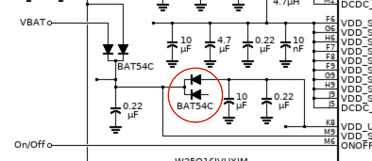
While I'm on the schematics, where is this diode connected to? It's floating in the current schematic? Is it just paralleled for current handling?

Screen Shot 2020-03-09 at 12.11.15 pm.png
 
That extra diode is unused. It really is unconnected, as the schematic shows.

The BAT54C comes with 2 diodes inside 1 package. The design needs 3 diodes. It's one of those strange quirks of modern semiconductors where 4 diodes (as 2 dual diodes parts) are smaller and less expansive than using the required 3 diodes. So 4 are in the design the 4th is simply left unused.

Thanks Paul - learning more every day!
 
Status
Not open for further replies.
Back
Top