breakout board for audio project

Status
Not open for further replies.

sboldrini

New member
Hi, I'm working on my own teensy 4.0 breakout board based on this one https://www.pjrc.com/breakout-board-for-teensy-4-0/
I've seen which pins are used by the audio board (mine is rev d) here https://www.pjrc.com/store/teensy3_audio.html
My question is: do I also need to connect all the other pins (0, 1, 2, 3, ...) from the teensy board to the audio board?
I'm also wondering if the pins used by the audio board (6, 7, 8, 10, ...) can be used as digital i/o, or if they are to be considered "disabled", but I guess the latter.

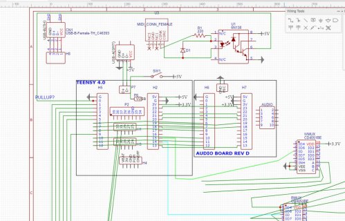
This is what my circuit looks like so far. I know it might be a mess, but it's my first schematic ever ;)
Desktop Screenshot 2020.03.12 - 15.14.07.17.jpg

Thanks to anyone that will reply to this thread :D

(I hope this is the correct place for this kind of questions)
 
You need to connect the power pins (ground pin, 3.3v, maybe vin), the I2S pins (7, 8, 20, 21, and 23), and the I2C pins (18, and 19).

If your audio board does not have I2C control, you don't need to connect pins 18/19. If you do connect the I2C pins, you may need 2.2K pull-up resistors, one 1 resistor between pin 18 and 3.3v, and the other between pin 19 and 3.3v.

On the audio shield are two SPI devices. If you connect either device, you need to connect the 2nd ground pin (next to pin 0). The SPI pins are 11, 12, and 13. You will also need to connect pin 10 if you wish to use the micro-SD reader, and pin 6 if you wish to use the flash memory that you can solder to the audio shield.

Note, Paul has said the wires to the audio shield (particularly pin 23) should be as short as possible, and that it is better to have the audio shield on top of the Teensy, avoiding jumper wires.

The audio shield has pin 15 wired up to be used as a potentiometer with resistors and capacitors that you can attach to the audio shield. This might be problematical if you want to use pin 15 for something else and use the PJRC audio shield (for example, if you want to use S/PDIF with Teensydunio 1.52 beta 1).

Other pins not mentioned are not needed by the audio shield.

If you are using an audio device, you cannot use the I2S pins (7, 8, 20, 21, 23) for other purposes.

If you are doing your own device, you could use the second I2S bus (pins 2, 3, 4, 5, and 33).

In addition, there are 3 other I2S pins (6, 9, and 32) that can be used if you do direct I2S control.
 
First of all thank you for your reply.

Paul has said the wires to the audio shield (particularly pin 23) should be as short as possible
maybe rotating the audio shield 90 or 180 degrees counter-clockwise would help? the wire would be just a couple centimeters long, is it short enough?

it is better to have the audio shield on top of the Teensy, avoiding jumper wires.
my idea was to place the teensy board and the audio shield next to each other, with the pins connected via the pcb wire, but i think i'll stick to what Paul says.

Other pins not mentioned are not needed by the audio shield.
If you are using an audio device, you cannot use the I2S pins (7, 8, 20, 21, 23) for other purposes.
If you are doing your own device, you could use the second I2S bus (pins 2, 3, 4, 5, and 33).
In addition, there are 3 other I2S pins (6, 9, and 32) that can be used if you do direct I2S control.

So, if i understood correctly, in any case I'm free to use pins (0, 1, 2, 3, 4, 5, 9, 14, 16, 17, 22, 24-33, 34-39) for potentiometers(on the analog pins), buttons, multiplexers etc.

In my case, since I'm building a modular synth similar to this one (https://www.pjrc.com/polymod-polyphonic-digital-modular-synth/)
but with some differences, such as:
- midi input instead of a built-in keyboard,
- line level audio input to connect a pre-amped instrument, such as a guitar or bass and play it through the effects of the audio library
- maybe mic input for a vocoder function
- sd card to store sample sounds such as drums, or to record something, or even to use a looper function
- maybe flash memory for enhanced delay effects
- up to 64 connectable modules
- maybe rgb controller

I've already written most of the code (which I'll share on this forum once tested) and I calculated that I need at least 1 analog and 23 digital pins in total, plus those taken by the audio shield.

Thank you again :)
 
sboldrini- did you end up finishing the project? I am building something similar and would love to compare notes. I am curious if you used the module library too?
 
Status
Not open for further replies.
Back
Top