I2C woes -

Status
Not open for further replies.

AverageGuy

Well-known member
I'm trying to get an I2C board working. It doesn't. Neither do two other boards. The LC doesn't see anything on the I2C bus. I'm using the following code to test:
Code:
/*********
  Rui Santos
  Complete project details at https://randomnerdtutorials.com  
*********/

#include <Wire.h>
 
void setup() {
  Wire.begin();
  Serial.begin(115200);
  Serial.println("\nI2C Scanner");
}
 
void loop() {
  byte error, address;
  int nDevices;
  Serial.println("Scanning...");
  nDevices = 0;
  for(address = 1; address < 127; address++ ) {
    Wire.beginTransmission(address);
    error = Wire.endTransmission();
    if (error == 0) {
      Serial.print("I2C device found at address 0x");
      if (address<16) {
        Serial.print("0");
      }
      Serial.println(address,HEX);
      nDevices++;
    }
    else if (error==4) {
      Serial.print("Unknow error at address 0x");
      if (address<16) {
        Serial.print("0");
      }
      Serial.println(address,HEX);
    }    
  }
  if (nDevices == 0) {
    Serial.println("No I2C devices found\n");
  }
  else {
    Serial.println("done\n");
  }
  delay(5000);          
}
The first board I tried was an HCU21D using a sample code from SparkFun. It printed 998 for temp and humidity. That said it wasn't working. So I tried the above code. It responded with:
Code:
canning...
Unknow error at address 0x01
Unknow error at address 0x02
Unknow error at address 0x03
...
Unknow error at address 0x7D
Unknow error at address 0x7E
No I2C devices found
printing the "Unknow" line for each address fro 0x01 to 0x7e. I don't English is the native tongue of the author of the code.

So I went off and grabbed a brand new gy21 p. Same result. A gy68 (bmp180) also doesn't work.

I have the devices connected as
Teensy LC pin 18 - Module SDA
pin 19 - Module SDC
pin 3V - Module VCC
pin GND - Module GND

I have two 4.7K pullups connected to the SDA and SDC pin from pin 3V.

To further complicate things, I also attempted to use both an ESP32 and ESP8266 to connect to the I2C devices with similar results.
I also removed the pullups

All parts were in their static shielded envelops before they were removed and tested.

I'm at a loss and thought this forum has some of the brightest folks I know, so here I am.
Screenshot at 2020-03-20 12-07-34.png

Any ideas?
Thanks,
Jim
 
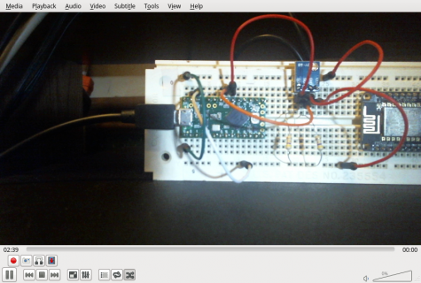
The colour bands on the resistors in the photo do start with 4 and 7, but the third band doesn't look red (4.7k). It looks more like yellow (470k).

Pete
 
Do you have a part number for which device you are actually using? You mention Sparkfun, but I don't see any HCU21D

Adafruit has: https://www.adafruit.com/product/1899 (HTU21D)...

I would check things like what are the specs for your device? Does it need +5v passed in to it's VCC and then has it's own VR to convert or can you pass in 3.3v. I
Does it have it's own set of Pull Up resistors? If so connected to what voltage? i.e. is this device setup to mainly work with old Arduino at +5v and you need to pass in +5v on VCC and potentially need to do voltage level conversions on SCL and SDA?
 
The colour bands on the resistors in the photo do start with 4 and 7, but the third band doesn't look red (4.7k). It looks more like yellow (470k).

Pete
That's pretty close to the right answer. It turns out that the drawer that contained those 4.7 Ohm resistors was marked as 4.7 K. I didn't look at the colors. My eyesight isn't what it was when I was young so I have to use a magnifier to read color codes these days. That's a good excuse anyway.

Thank you all for the help.

It's working now.
Jim
 
I was using the SparkFun library and yes it's an HTU21D. Did I mention my eyesight wasn't real good these days? :eek:
 
I too am a little frustrated with the Wire library. I'm using two kinds of temperature sensors (a TC74 and a TMP102 from Sparkfun) and I can't either of them to work. Tried all sorts of things including the scanner shown above, but they just won't work.

Tried both 10k and 1K external pull-ups. Not a peep.

I usually program the I2C receiver "by hand" on the old AVR Teensy, but I thought I'd give the Teensyduino a try. So far it has its ups and downs. I got the Bluetooth receiver to work on the Serial port, but the I2C devices are giving me problems.

In the code below I'm trying to readout the TMP102 "by hand" (not using the TMP sensor library).

Can anyone spot the problem?

Code:
#include <Wire.h>
#include <WireIMXRT.h>
#include <WireKinetis.h>
#include <SparkFunTMP102.h>

#include <Time.h>
#include <TimeLib.h>

#include <SPI.h>

//TMP102 sensor0(0x48);

void setup() 
{
  Serial.begin(9600);

  while (!Serial) 
  {
  }

  Wire.setSDA(18);
  Wire.setSCL(19);

  Wire.begin(); //Join I2C bus as master

  // prints title with ending line break
  Serial.println("Teensy Thermostat Debug Output");

  //digitalWrite(LED_BUILTIN, HIGH);
}

void loop() 
{
  float temperature;

  //Serial.print("Waking up...\n");
  
  //sensor0.wakeup();

  Wire.beginTransmission(0x48);
  Wire.write(0);
  Wire.endTransmission();
  Wire.requestFrom(0x48, 2);
  if (Wire.available() > 0)
  {
    byte tempL = Wire.read();  
    byte tempH = Wire.read();  
    Serial.print("Byte read: ");
    Serial.println(tempL);      
    Serial.println(tempH);      
  }
  else
  {
    Serial.println("Failed to read from temperature sensor");
  }
    
  //delay(200);
  //digitalWrite(LED_BUILTIN, LOW);
  //delay(200);

  //Serial.print("Reading temperature...");
  //temperature = sensor0.readTempC();
  //Serial.println();
  
  //Serial.print("Going to sleep...\n");
  //sensor0.sleep();

  //Serial.print("Temperature: ");
  //Serial.print(temperature);
  //Serial.println();

  delay(1000);  // Wait 1000ms
}
 
Last edited:
The Sparkfun TMP102 board has built-in 4.7k pullup resistors so you don't need to add them. Try it without them.
Also, pins 18 and 19 are the default I2C pins. Comment these two lines - probably won't help but can't hurt.
Code:
  Wire.setSDA(18);
  Wire.setSCL(19);

Pete
 
I'm using the TMP102 without pull-ups (tried them with pull-ups as well) and commenting out those two lines unfortunately don't make a difference.
 
I haven't got a TMP102 but I tried the scanner code in message #1 on a Teensy LC and it finds all 5 addresses that I have on a board here - Chronodot real-time clock (2 addresses), EEPROM (2 addresses) and a counter.
The code works, so the problem is somewhere in your hardware setup. Are you sure that you've got SDA and SCL wired correctly? (I had it wrong the first time I tried the scanner).

Pete
 
have you tried using the sparkfun library? their example uses sensor0.wakeup() before reading temp regs. your manual mode does not do the wakeup??

though if you can't get i2cscanner to work, you need to solve that first.
 
have you tried using the sparkfun library? their example uses sensor0.wakeup() before reading temp regs. your manual mode does not do the wakeup??

though if you can't get i2cscanner to work, you need to solve that first.

If it's a hardware fault that would mean that two TC74's and two TMP012 boards would all be defective. That would be a unicum.
 
Hello,

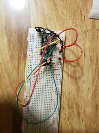
it is very difficult to see in the photo, but at the soldering points of the teensy it looks as if there is a short circuit between D18 and D19 (SDA, SCL).
 
I found the problem! You won't believe this but the culprit was actually the green wire, it was defective. I couldn't find any physical damage to it but the continuity tester showed it was open.

I replaced the wire and the I2C detector immediately found the TMP102.

Thanks everyone for your help!

BTW: the TC74 turned out to be a 5V part. That may explain it not working with the 3.3V Teensy.
 
Last edited:
Status
Not open for further replies.
Back
Top