T3.2: Best/advised way to read bipolar input on A0

Status
Not open for further replies.

prensel

Member
Hello everyone,

I've been using the teensy 3.2 for a while and recently started using analog inputs.

I'm facing reading a bipolar signal +/- 1.5 volt generated by a LEM current transducer.
The LEM reads max +/- 300A and outputs +/-150mA over a 10R resistor, 1:2000 (1mA = 2A)

What is the best/advised way to read and adapt this LEM output signal into the teensy on A0 ?

I have found 3 options sofar:

#1: Using a low noise opamp according to this: https://masteringelectronicsdesign.com/measure-a-bipolar-signal-with-an-arduino-board/

#2: using a 10k/10k voltage divider between 3v3 and GND and superimposing the LEM output onto the midpoint using a resistor

#3: using a 10k/10k voltage divider between 3v3 and GND and connecting the LEM signal using a 10uF capacitor to the midpoint

Any suggestion or recommendations ?

Regards,

Paul
 
Hello,

bear in mind to use differential analog inputs at A10/A11 or A12/A13 of teensy3.2 with ADC library.
So you might not have to adapt bipolar to unipolar. Also check posibilties for external reference voltage for teensy in lib.
 
Thanks for your reply.

Unfortunally i'm tied to using the A0 or A1 because of the implementation of the teensy in my project.

I currently having a hard time getting the op amp variant to work before connecting it to the teensy.
I'm using a Traco TMR6-1223 +/- 15V module and an OPA277 high precision op amp in a non-inverting setup.
With Rin=10R between Traco isolated GND and -In and Rf = 0K (direct wire) between Output and -In.
The LEM output is connected over a Rm of 10R to isolated GND and to +In.
I also have decoupled V+ and V- using two 100nF capacitors on the isolated GND of the Traco.
When looking at the op amp output port it is not a very stable signal, jumping around and not lineair compared to the input voltage over Rm.
 
Wow! 150mA across a 10-0hm resistor is going to dissipate 1.5Watts at full scale. I hope that resistor is big and temperature-stable.

If you have access to that part of the circuit, you might consider changing the 10 Ohms to 100 Ohms to reduce the dissipation in the resistor.

Then you can add a voltage divider to bring the output voltage down to a level you can work with on the Teensy.

If you use your Option #2 you can change that voltage divider to both step down the current and add in the necessary offset.

With resistors in the 10K Ohm range, you probably need a capacitor at the ADC input to store charge, else your sensed voltage will
vary with your sampling rate.
 
If i'm correct P will only be 0.15A * 0.15A * 10R = 0,225W ? Not that big of an issue i guess for a regular 1/4 W resistor ?

Changing the 10R is not going to work because the LEM is a current transducer so it will still be outputting 150mA per 300A as long power is sufficient.

I have tried the #2 option with R in the 100K range (240K/470K divider on +5V) but I assume these R's are too high to get a stable reading at the A0 port of the Teensy.
Will make a test with lower R values and add a C on the A0 port to GND. Any recommends on the C value ? will 100nF be enough ?
 
Sorry about the error in the power dissipation calculation. I should have caught that, especially since I've been using a high-side current sensor based on the Max 471 to do measurements of Teensy power dissipation for several weeks now.
It works the same way as your LEM and I've changed the output resistor to give higher sensitivity at lower currents.

You may be able to get stable readings with a pretty high resistance in your voltage divider by adding a capacitor to ground at the A0 ADCinput. The basic principle is that many ADCs (and I hope the Teensy is one) work by charging an input capacitor, then do a charge-balancing act with a series of other internal capacitors to determine the voltage. If you have a high input impedance, the ADC input capacitor cannot fully charge during the short window when it is connected to the input pin. The ADC part of the Kinetis reference manual recommends a 0.01uF capacitor placed close to the ADC input pin and connected between the pin and analog ground. This capacitor provides a charge reservoir to make sure that the input pin can fully charge the ADC input capacitor.

The down side of having a 100K input impedance and the 0.01uF capacitor is that you have to limit your sampling rate so that the 0.01uF cap is fully charged to the input voltage between conversions.

Here's a bit of early-morning, pre-caffeine math which I hope you will verify:

RC time constant at input: 1x10^5 x 1 x 10^-8 = 1 x 10^-3 or 1 millisecond. If you allow 3 time constants for the capacitor to fully charge, that means limiting your sampling to about 333 samples per second.
if you need faster sampling, you could stick with the higher impedances in your offset circuit and add a simple voltage follower between the circuit and the ADC. If you use a rail-to-rail single-supply op amp, it is a simple circuit, but check the specs for input and output near zero volts if you have to measure very low currents.
 
Last edited:
I finally got some stability today after fiddeling around and wasting time with the opamp and experimenting with different R and C components.
At some point even hoovering my hand over the bb resulted in erroneous analog readings..

So I decided to rebuild the stuff on some perfboard and changed the R divider to 10K/22K fed by the same +5V (from a R785.0-1.0) that powers the Teensy.
On the midpoint I attached the 0 (GND) from the Traco +/- 15V DCDC converter and connected the LEM output to 10R burden resistor connected to the same midpoint.
The LEM output or 'positive' side of the burden resistor is also connected in series with a 10K to the A0 pin and also a 100nF cap to GND. This setup gives fairly good results.
The 10K is connected to GND so the midpoint is offset at 10R/(10R+22R) * 5V = 1563mV. This gives me a possible range of +/- 1563mV/10R * 2000 = +/- 312.600mA (+/- 312Amps).

The offset is currently programmed as a constant in the software but i'm thinking of making this a variable calibration value to determine some drifting caused by dissipation or parts tolerances.
 
RC time constant at input: 1x10^5 x 1 x 10^-8 = 1 x 10^-3 or 1 millisecond. If you allow 3 time constants for the capacitor to fully charge, that means limiting your sampling to about 333 samples per second.
if you need faster sampling, you could stick with the higher impedances in your offset circuit and add a simple voltage follower between the circuit and the ADC. If you use a rail-to-rail single-supply op amp, it is a simple circuit, but check the specs for input and output near zero volts if you have to measure very low currents.

In the testbed I now have 10K and 100nF so with 3 Tau its about 0.3mS per sample or 3333 samples/S.
Does the analogRead 'empty' the internal caps on every command execute ?

The analogRead is now in the main loop but I can throw in a elapsedMillis variable to take a reading every 100mS or so.
 
In answer to your question:
Does the analogRead 'empty' the internal caps on every command execute ?

I don't think it empties the internal cap, but it does siphon off some of its charge to the internal capacitors.

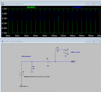
I think you can use a simple circuit like this:
Level_Shift.png

This circuit sends a voltage between ~0.0 and 1.2V to the ADC. If you set up the ADC to use the internal 1.2V reference, you can get the full 0 to 4095 counts range of a 12-bit conversion. The input is low impedance and you can adjust the offset with the T3.2 DAC output on pin A14.

This afternoon, I'll try to put together a sketch illustrating the setup and run some tests with my signal generator sending a +/- 1.5V square wave.
 
Here is my test sketch and the results.
The input was a signal generator set to produce a square wave alternating between -1.5 and +1.5V at about 9.8Hz
Code:
/********************************************************
 * Teensy 3.2 test offset and scaling of  -1.5 to 1.5V signal
 * MJB  3/27/20
 */

#define AREF 1.2
void SetDAC(float v){
uint16_t dcount;
  dcount = (uint16_t)((v/AREF) * 4095);
  Serial.printf("DAC Count set to %u\n",dcount);
  analogWrite(A14,dcount);
 
}
void setup() {
  // put your setup code here, to run once:
  uint16_t dacval;
  Serial.begin(9600);
  analogWriteResolution(12);
  analogReadResolution(12);
  // Note: increasing the averaging reduces the input impedance of the 
  // ADC and you may need a capacitor from A14 to ground
  analogReadAveraging(4);
  analogReference(INTERNAL); // use 1.2V internal reference on T3.2

  delay(200);
  Serial.println("Teensy 3.2 offset and scaling test");
  SetDAC(1.05);  // Set 0.95 V output
}

void loop() {
  // put your main code here, to run repeatedly:
  ShowAnalog(160, 3);
 
  delay(1500);
  
}

void ShowAnalog(uint16_t samples, uint16_t intervalmSec){
  uint16_t i;
  float vsamps[1000];

  if(samples > 1000) samples = 1000;
  for(i=0;i<samples;i++){
      vsamps[i] = 1.2* analogRead(A0)/4095.0;
      delay(intervalmSec);
  }
  Serial.printf("\n\nData sampled at %6.2f samples/second\n", 1000.0/intervalmSec);
  // now show the results in lines of 16 values
  for(i= 0; i<samples; i++){
    if((i%16)== 0) Serial.println();
    Serial.printf("%6.3f ", vsamps[i]);
  }
  Serial.println();
  
}

Here are the results:
Code:
Data sampled at 333.33 samples/second

 1.164  1.167  1.157  1.160  1.160  1.166  1.165  1.159  1.158  1.162  0.032  0.026  0.036  0.030  0.027  0.035 
 0.028  0.034  0.038  0.035  0.029  0.029  0.031  0.039  0.029  0.026  0.033  1.162  1.162  1.165  1.168  1.158 
 1.165  1.158  1.168  1.164  1.156  1.161  1.157  1.157  1.164  1.162  1.165  1.160  0.036  0.036  0.030  0.028 
 0.027  0.035  0.032  0.029  0.026  0.026  0.031  0.023  0.027  0.033  0.034  0.026  0.331  1.164  1.161  1.160 
 1.159  1.159  1.162  1.163  1.168  1.168  1.164  1.162  1.160  1.158  1.166  1.165  1.159  0.036  0.033  0.028 
 0.024  0.031  0.030  0.030  0.028  0.035  0.030  0.030  0.030  0.026  0.030  0.032  0.032  0.024  1.158  1.164 
 1.167  1.161  1.164  1.164  1.156  1.164  1.164  1.160  1.158  1.156  1.164  1.160  1.162  1.159  1.162  0.026 
 0.035  0.034  0.022  0.029  0.030  0.030  0.031  0.036  0.032  0.036  0.030  0.028  0.027  0.035  0.033  0.030 
 1.169  1.161  1.163  1.164  1.166  1.161  1.160  1.162  1.165  1.157  1.164  1.164  1.169  1.161  1.157  1.162 
 0.026  0.023  0.025  0.030  0.028  0.037  0.032  0.028  0.027  0.028  0.033  0.030  0.031  0.031  0.026  0.026

You can see that there is 5-6mV of noise. Part of that is probably due to running the test with the T3.2 on a plug-in breadboard. Those boards make it difficult to get good analog results. Disconnecting my scope probes and signal generator and grounding the input still leaves 3 to 5mV of noise. If you need 1mV noise levels, you'll need filtering at the ADC input and have to live with the phase delays that will cause.

Putting a 47nF capacitor from A14 to ground did reduce the noise, but I suspect that would limit the sampling rate.
Code:
Data sampled at 333.33 samples/second  47nF capacitor from ADC input to ground

 0.030  0.030  0.031  0.031  0.031  0.032  0.031  0.031  0.032  0.032  1.165  1.165  1.166  1.165  1.165  1.163 
 1.163  1.164  1.164  1.163  1.162  1.162  1.163  1.162  1.162  1.162  1.163  0.031  0.033  0.030  0.030  0.031 
 0.031  0.034  0.030  0.031  0.031  0.032  0.033  0.055  0.031  0.031  0.031  0.032  1.164  1.165  1.165  1.165 
 1.164  1.162  1.164  1.164  1.163  1.162  1.163  1.163  1.163  1.164  1.162  1.163  1.161  0.031  0.029  0.030 
 0.030  0.030  0.030  0.030  0.030  0.031  0.032  0.032  0.032  0.031  0.030  0.032  0.032  1.164  1.165  1.165 
 1.164  1.164  1.163  1.165  1.164  1.163  1.163  1.162  1.162  1.163  1.164  1.163  1.162  1.162  0.030  0.029 
 0.030  0.030  0.031  0.031  0.030  0.030  0.032  0.032  0.031  0.031  0.030  0.032  0.031  0.032  0.032  1.166 
 1.165  1.165  1.164  1.164  1.164  1.164  1.162  1.163  1.162  1.162  1.164  1.163  1.163  1.162  1.162  1.162 
 0.028  0.029  0.030  0.030  0.031  0.030  0.030  0.031  0.032  0.032  0.032  0.031  0.031  0.032  0.031  0.031 
 1.077  1.165  1.165  1.164  1.164  1.163  1.164  1.163  1.162  1.162  1.162  1.162  1.163  1.163  1.162  1.162
 
Adding a 'delay' with an elapsedMillis in the main loop improved the readings somewhat.
The offset constant is set at 1555mV (so not exactly the 1563 as calculated before since using 5% R) and the 'dynamic offset' varies from 1555mV and 1557mV between non-zero readings
The non-zero Amp readings have a variance of 5 - 10mV per same amount of current passing the sensor.
I'm using 12 bit precision so 2048 values get mapped for either + and - range of 1563mv values. Each 1mV resembles 0,1mA * 2000 = 200mA. So 5mV per 1A.
With the variance of 5-10mV means 1A-2A error in the reading per 300A is about 1,5%.
 
I need to take a close look at your tests and will certainly do but lack of time and other issues regarding my pile of coding for the last 30 year orso got me busy working on a version control system (SVN at last).

Did however change the R on the A0 input from 10K to 1K to get some better results and as it looks now the readings are pretty stable. At least good enough for now.
When using the breadboard I got strange and offset readings but since using a decent piece of proto PCB that all went away.
 
Status
Not open for further replies.
Back
Top