Suggestions for a replacement display please.

Status
Not open for further replies.

AJL Electronics

Active member
My current project
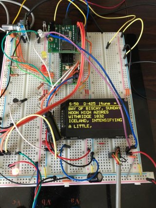
IMG_4964.jpg

uses an OLED SPI display on a Teensy 3.6 with audio adapter board, this one: 2.42" inch SSD1309 128x64 SPI OLED LCD Graphic Display Module Which works fine. The only issue I have is the RFI it puts out and I would like something a little bigger, perhaps 4.3" or even 5".

I bought this TFT without reading the page properly: 3.5" TFT LCD Display Module 480x320+ Touch Panel. I didn't realise until it arrived that it was a shield, nor did I realise that it wasn't SPI or I2C. I have had it working on a Uno but with so many pins required I can't use it on my Teensy 3.6 project.

My question then is which display module you would suggest that will not be too much work to substitute for the OLED? RGB colour is not needed although I would likely make use of it. This one caught my eye: 5" 5.0 inch TFT LCD Module Display,w/RA8875,Touch Panel,I2C,Serial,SPI,Tutorial but with funds being less fluid at the moment, I would rather not waste my money!

The other idea running around my head was to use the 4.3" TFT I bought, with the Uno and feed it serial data from another serial port on the Teensy maybe?
 
I've never used that display, but i'm looking into Nextion's. I currently use 2.8" TFT (ILI9341) and have had great success. I recently purchased a 3.5" SPI had have it working as well. But these may be too small for your needs.

links
https://www.amazon.com/gp/product/B07W84SX8K/ref=ppx_yo_dt_b_search_asin_title?ie=UTF8&psc=1
https://www.amazon.com/gp/product/B017FZTIO6/ref=ppx_yo_dt_b_search_asin_title?ie=UTF8&psc=1


The 2.8' can share the touch, SD and display SPI pins. the 3.5" needs separate touch pins.

Not sure this helps.
 
@AJL
This 3.5'' display could be connected as SPI, if you change the interface mode of the controller. See the Dataseet:
https://www.displayfuture.com/Display/datasheet/controller/ILI9486L.pdf
Page 26 of the PDF.

Surely, you'll have to take the shield apart to do the mod.

The audio board needs hevy mods to silence the power supplies and signals enough so the audio is clean.
Instead of using pins to connect the board to the Teensy, use carbon resistors on the data lines. Something about 156 to 220Ω is fine, but choose one value for all. This helps. Also some metal resistors of 47Ω for the power and ground lines, and then 47nF and 1μF in parallel to ground. That silences it.
 
Oh, I forgot: flying wires produce and collect lots of RFI. Keep then as short as almost impossible. If you need to use them, use 47Ω carbon resistors on both ends instead of pins. This helps keem the rf spectrum a bit cleaner. It must be carbon resistors, because metal ones have too high inductivity, that could skew the signal too much.
 
Thanks both, that is very helpful.

I know about RFI, it was my job in the 80s and having been a Radio Amateur ever since, I have some experience. The RFI on this one definitely comes from the display, with a 20x4 LCD it is whisper quiet. No doubt there is some radiated noise from the interconnects, that is only to expected until it is rebuilt properly. Your tips on the suppression are gratefully received and will be built into the final version.

I stacked the boards like that after failing to get it to work with them one behind the other. That was probably me making some daft error though, as I get older my brain seems to struggle with simple matters!

The final version will be with boards for input filtration etc in separately cased modules with feedthrough capacitors etc.

I already have the case I want to use on my shelf, which is why I am specifying no bigger than 5".

Thanks again

DE G6FGO
 
The audio board does not work without the said resistors in the lines, if set at the side of Teensy on a breadboard. With the resistors, it does. That is the ringing effects on the wires, that distort the signals enough to disable the digital circuit or lead to its malfunction. The same hapepns with SPI displays at high bus speeds that do not work on a breadboard, but with dampening in-line resistors it does.

Yes, an OLED can produce a lot of noise and definitely needs shielding and decoupling, like any multiplex LED matrix. One way could be to use a second voltage regulator only for the display, so the supply rail does not ring back to the rest of the circuit.
 
Very interesting. I did some investigation with my "sillyscope" but couldn't find the issue. I am very grateful for your advice, thanks muchly.
 
Status
Not open for further replies.
Back
Top