FlyinSkwerl
Member
Hi Folks,
This will my first project with Teensy, I've messed with a Razz Pi for a CS4 course so I believe the learning curve won't too bad. For the project I have chosen a Teensy 3.5 which should arrive by the end of the week.
Let me start by introducing my project:
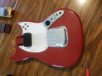
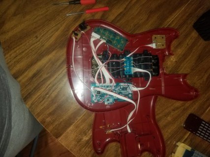
I bought a Rock Band 3 Mustang Wii Guitar Controller from amazon to fool around with. I don't have a Wii and various sources cited it should have been midi capable (it has a built in midi port) out of the box. After a full day and a half messing with configurations/settings/drivers etc, I can't get anything but an active sensing signal on the midi. I believe it has something to the pairing routine that the Wii uses, preventing the controller from fully starting up to process midi signals, it could also be a manufacture issue (bought it new). I don't really care about the wii/wireless capability and have seen quite a few midi arduino projects around online. So the idea in a nutshell is to gut the internal chip and replace it with a Teensy.
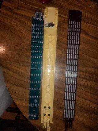
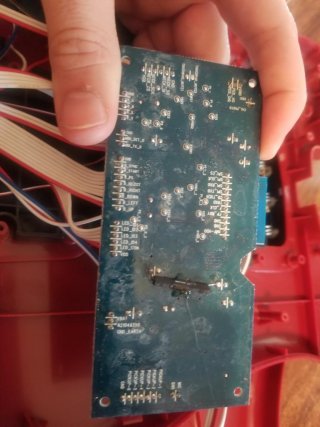
The "string" inputs and body buttons should be very easy to interface with the Teensy, and I'm not worried about the midi aspect of the project. There is a teensy problem (bet you've never heard that one) when it comes to the 150+ button fret board. The board multiplex's a resistor/diode matrix that is connect to the 150+ buttons into a micro-controller chip, that then communicates with the main board in the guitar body. I was about to give up the idea of the project until I flipped over the main board and saw that the pins to the micro-controller were labeled SO, SI, SCK, and CS. A quick google search resulted with SPI and I did a little research into how SPI works.
This brings me to the purpose of my post:
I have an SPI device that I want to interface the Teensy with and have no idea how it is configured, I don't even know if the device is the master or slave device.
What I want to accomplish:
1. Determine the SPI configuration so I can interface the Teensy to the micro-controller.
2. Analyze the communication from the micro-controller to understand what message, for example, what is sent via the buttons.
3. Create a program to use the commands and send midi signals.
Right now my game plan is to:
1. Make a small side project to orient myself with Teensy and ensure my setup works (ei wiring and computer communication)
2. Create a program that can display information from the Teensy spi (bus?) onto the computer (or at worst somehow create logs of the information to view).
3. Use the program to attempt combinations of SPI settings until I get lucky and I see relevant communication happen (I'm hoping to improve this part of the plan)
4. Analyze the SPI messages while hitting buttons etc and determine the format of the communication
5. Use the info to build my midi controller
As mentioned above I am hoping to improve Step 3, and get idea of how feasible it would be to accomplish such a task.
Any direction in maybe how to maybe better figure out the SPI configuration would definitely be appreciated.
I don't have any code as I don't even have the Teensy yet. I'm just trying to get ideas and maybe hammer out the game plan a bit while I wait for it to arrive.
I have include few pictures below of what I plan on working with, Thanks in advance for any assistance .
.


This will my first project with Teensy, I've messed with a Razz Pi for a CS4 course so I believe the learning curve won't too bad. For the project I have chosen a Teensy 3.5 which should arrive by the end of the week.
Let me start by introducing my project:
I bought a Rock Band 3 Mustang Wii Guitar Controller from amazon to fool around with. I don't have a Wii and various sources cited it should have been midi capable (it has a built in midi port) out of the box. After a full day and a half messing with configurations/settings/drivers etc, I can't get anything but an active sensing signal on the midi. I believe it has something to the pairing routine that the Wii uses, preventing the controller from fully starting up to process midi signals, it could also be a manufacture issue (bought it new). I don't really care about the wii/wireless capability and have seen quite a few midi arduino projects around online. So the idea in a nutshell is to gut the internal chip and replace it with a Teensy.
The "string" inputs and body buttons should be very easy to interface with the Teensy, and I'm not worried about the midi aspect of the project. There is a teensy problem (bet you've never heard that one) when it comes to the 150+ button fret board. The board multiplex's a resistor/diode matrix that is connect to the 150+ buttons into a micro-controller chip, that then communicates with the main board in the guitar body. I was about to give up the idea of the project until I flipped over the main board and saw that the pins to the micro-controller were labeled SO, SI, SCK, and CS. A quick google search resulted with SPI and I did a little research into how SPI works.
This brings me to the purpose of my post:
I have an SPI device that I want to interface the Teensy with and have no idea how it is configured, I don't even know if the device is the master or slave device.
What I want to accomplish:
1. Determine the SPI configuration so I can interface the Teensy to the micro-controller.
2. Analyze the communication from the micro-controller to understand what message, for example, what is sent via the buttons.
3. Create a program to use the commands and send midi signals.
Right now my game plan is to:
1. Make a small side project to orient myself with Teensy and ensure my setup works (ei wiring and computer communication)
2. Create a program that can display information from the Teensy spi (bus?) onto the computer (or at worst somehow create logs of the information to view).
3. Use the program to attempt combinations of SPI settings until I get lucky and I see relevant communication happen (I'm hoping to improve this part of the plan)
4. Analyze the SPI messages while hitting buttons etc and determine the format of the communication
5. Use the info to build my midi controller
As mentioned above I am hoping to improve Step 3, and get idea of how feasible it would be to accomplish such a task.
Any direction in maybe how to maybe better figure out the SPI configuration would definitely be appreciated.
I don't have any code as I don't even have the Teensy yet. I'm just trying to get ideas and maybe hammer out the game plan a bit while I wait for it to arrive.
I have include few pictures below of what I plan on working with, Thanks in advance for any assistance


