Hi,
This is my first post. I'm often coming back to the forum to pick info, now it's time to jump in!
I'm back to electronics after years of inactivity in that field and I might be a little rusted, so I'm looking for a little help to check my work.
Here is my problem to solve:
- Reading 10-322 / 10-180 ohms automotive resistive sensors (Temp/pressure)
- Lowest possible cost (only basic components for no "extended parts" on production line of the PCB)
- Protected
- SMT
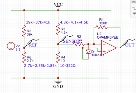
Here is the approach I tried to build (cf schema and simulation attached):
- LM324 cheap Op Amp (7cts for a quad package) used as inverted amplified in single supply (3.3V)
- Inverted amplifier for virtual ground with low current, Basic reference voltage with divider
- Voltage Divider with sensor as lower part of it
- Protection diode basic (no Schottky) from sensor input (middle of divider) to reference voltage instead of the classic Vcc so that it triggers way before VCC = 3.3V (reference is in the 0,230-0,260V)
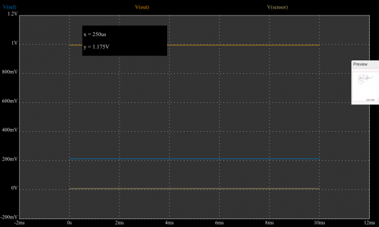
- Depending on luck with resistors, output range goes from 50mv to 1,1V down to 350MV to 890MV in narrowest case
- Teensy 3.6 ADC on 1.2V reference, in worst case more than half of the range is still usable: much more than what I need (1000 values would be enough, that leaves 4096)
Simulation at all min/max values of 5% resistors shows Vout always in 50mv - 1.2V range, op amp within in and out ranges. System seems to survive 90V en Sensor input.
Is there something wrong with those assumptions ? Do I miss something (or everything )
)
Many thanks in advance!
KR
François


This is my first post. I'm often coming back to the forum to pick info, now it's time to jump in!
I'm back to electronics after years of inactivity in that field and I might be a little rusted, so I'm looking for a little help to check my work.
Here is my problem to solve:
- Reading 10-322 / 10-180 ohms automotive resistive sensors (Temp/pressure)
- Lowest possible cost (only basic components for no "extended parts" on production line of the PCB)
- Protected
- SMT
Here is the approach I tried to build (cf schema and simulation attached):
- LM324 cheap Op Amp (7cts for a quad package) used as inverted amplified in single supply (3.3V)
- Inverted amplifier for virtual ground with low current, Basic reference voltage with divider
- Voltage Divider with sensor as lower part of it
- Protection diode basic (no Schottky) from sensor input (middle of divider) to reference voltage instead of the classic Vcc so that it triggers way before VCC = 3.3V (reference is in the 0,230-0,260V)
- Depending on luck with resistors, output range goes from 50mv to 1,1V down to 350MV to 890MV in narrowest case
- Teensy 3.6 ADC on 1.2V reference, in worst case more than half of the range is still usable: much more than what I need (1000 values would be enough, that leaves 4096)
Simulation at all min/max values of 5% resistors shows Vout always in 50mv - 1.2V range, op amp within in and out ranges. System seems to survive 90V en Sensor input.
Is there something wrong with those assumptions ? Do I miss something (or everything
Many thanks in advance!
KR
François


