ToniPropeller
Member
Hello everyone,
I'm currently failing on a task that initially seemed easy... at least that is was I thought")
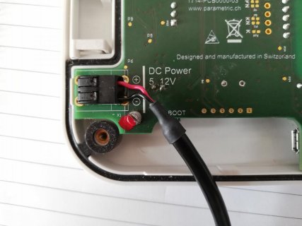
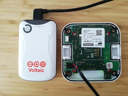
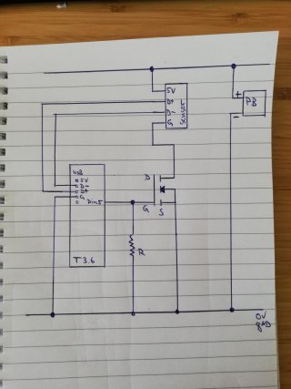
I have a sensor that is powered by a powerbank. I want to switch the sensor's power supply via the Teensy (it should be switched of over night to save power). When turned on, the sensor consumes between 70mA and 100mA at 5V.
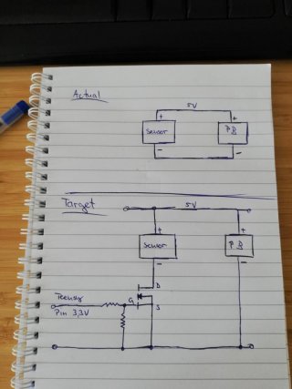
My plan is to use a MOSFET for this purpose but at the moment the sensor remains ON even when I remove the voltage from the gate using a IRLB8721 N-Channel MOSFET. My knowledge of the subject is somewhat rusty, as it seems to me, because reading about this topic confused me a lot with things like voltage difference, N-Channel vs. P-Channel MOSFET, low side vs high side switching and so on
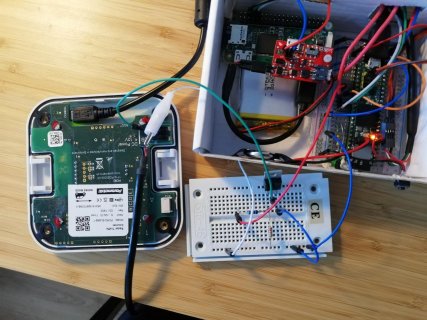
Would someone be kind enough to help me solve the problem? To be clear: This is more of a general question than a Teensy related one, because currently the Teensy isn't even involved, i'm just using it's 3.3V output pin for the gate volatage. In the attachment you will find a simple drawing of the part of the bigger circuit for the project as well as a simple photo of the sensor.
Thank you in advance,
Martin
I'm currently failing on a task that initially seemed easy... at least that is was I thought
I have a sensor that is powered by a powerbank. I want to switch the sensor's power supply via the Teensy (it should be switched of over night to save power). When turned on, the sensor consumes between 70mA and 100mA at 5V.
My plan is to use a MOSFET for this purpose but at the moment the sensor remains ON even when I remove the voltage from the gate using a IRLB8721 N-Channel MOSFET. My knowledge of the subject is somewhat rusty, as it seems to me, because reading about this topic confused me a lot with things like voltage difference, N-Channel vs. P-Channel MOSFET, low side vs high side switching and so on
Would someone be kind enough to help me solve the problem? To be clear: This is more of a general question than a Teensy related one, because currently the Teensy isn't even involved, i'm just using it's 3.3V output pin for the gate volatage. In the attachment you will find a simple drawing of the part of the bigger circuit for the project as well as a simple photo of the sensor.
Thank you in advance,
Martin