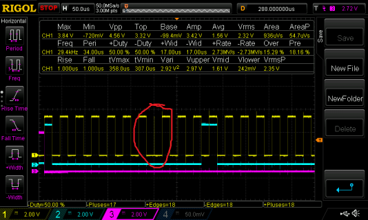
In the image above you can see the SCK output of my Teensy 3.6 represented by the yellow line, slave data from another device in blue, and the chip select output of my Teensy 3.6 in purple. I've encircled a worrying spike that appears after every 8 pulses - an extremely fast glitch pulse which is totally unwanted.
I've observed this behavior during SPI Master Mode communications if DMA is being used to output data. If you're trying to capture anything meaningful, that's a deal breaker since who knows how the slave device will respond to that glitch pulse.
Stranger still; setting the CONT_SCKE bit in the SPI_MCR register seems to relieve this problem but also makes the MISO data unreliable, so either way I'm having a lot of trouble capturing SPI data over DMA if I also DMA data outwards.
Perhaps there's something I've missed in the datasheet which would account for this issue?
Below is the code I used to get such a strange outcome. I'm attempting to capture continuous SPI data in a ping-pong DMA buffer and print out the results over Serial. `printPadded()` is a method I wrote to just print out the binary of a given integer so that I could easily compare against my oscilloscope (which is how I determine that the data is only close to correct if CONT_SCKE is disabled). I've also tried with the CPOL bit toggled to get a (toggled) equally incorrect result.
Code:
#include <Arduino.h>
#include "DMAChannel.h"
#include "global.h"

DMAChannel dma;
DMASetting dmaSetting0;
DMASetting dmaSetting1;
DMAChannel txdma;

#define BUFFLEN 9408 //that is not 147

volatile uint16_t buffer0[BUFFLEN];
volatile uint16_t buffer1[BUFFLEN];
volatile bool streamingBuf0;
bool streamingBuf0Shadow;

#define CSPIN 22
//sck = 13
//miso= 12

void dmaFinishedIsr() {
  dma.clearInterrupt();
  streamingBuf0 = !streamingBuf0;
}

void setup() {
  pinMode(CSPIN,OUTPUT);
  digitalWriteFast(CSPIN,HIGH);
  Serial.begin(115200);
  while (!Serial);

  //spi setup
  {
    SIM_SCGC6 |= SIM_SCGC6_SPI0;  //turn on spi0's clock
    SPI0_MCR = SPI_MCR_MSTR;//0;//~(SPI_MCR_MDIS | SPI_MCR_HALT);    //turn on the module
    SPI0_CTAR0 = SPI_CTAR_FMSZ(15) | SPI_CTAR_BR(0xA) | SPI_CTAR_CPOL;
    //DMA/Interrupt Request Select and Enable Register: set bits for rxfifo drain flag, txfifo underflow flag, txfifo fillable flag, tfff goes to DMA not interrupts
    SPI0_RSER =                                         SPI_RSER_RFDF_RE | SPI_RSER_RFDF_DIRS | SPI_RSER_TFFF_RE | SPI_RSER_TFFF_DIRS;

    SPI0_SR = SPI_SR_TFUF;       //w1c the transfer underflow flag just for fun

    // _VectorsRam[16 + IRQ_SPI0] = irqfunc;
    pinMode(11,OUTPUT);
    CORE_PIN12_CONFIG = PORT_PCR_MUX(2);                              //miso (data in, more like)
    // CORE_PIN10_CONFIG = PORT_PCR_PE | PORT_PCR_PS | PORT_PCR_MUX(2);  //cs
    CORE_PIN13_CONFIG = PORT_PCR_MUX(2);                              //sck
    // NVIC_SET_PRIORITY(IRQ_SPI0, 1); // set priority
    // NVIC_ENABLE_IRQ(IRQ_SPI0); // enable CS IRQ
  }

  {
    dmaSetting0.source((volatile uint16_t&)SPI0_POPR);
    dmaSetting0.destinationBuffer((volatile uint16_t *) buffer0, BUFFLEN*2);
    dmaSetting0.interruptAtCompletion();
    dmaSetting0.replaceSettingsOnCompletion(dmaSetting1);

    dmaSetting1.source((volatile uint16_t&)SPI0_POPR);
    dmaSetting1.destinationBuffer((volatile uint16_t *) buffer1, BUFFLEN*2);
    dmaSetting1.interruptAtCompletion();
    dmaSetting1.replaceSettingsOnCompletion(dmaSetting0);

    dma = dmaSetting0;
    dma.triggerAtHardwareEvent(DMAMUX_SOURCE_SPI0_RX);
    dma.attachInterrupt(dmaFinishedIsr);

    txdma.sourceBuffer((volatile uint8_t*)buffer0,1); // The data for which we wish to transmit and it's length
    txdma.destination((volatile uint8_t&)SPI0_PUSHR); // Move data into the SPI FIFO register
    txdma.triggerAtHardwareEvent(DMAMUX_SOURCE_SPI0_TX); // Only transfer data once the previous byte has been transmited (This is to ensure all bytes are sent)
    txdma.enable();
  }
  Serial.printf("waiting for a sec...\n");

  delay(2000); //2 seconds to allow the other module time to boot / prepare
  streamingBuf0 = true;
  streamingBuf0Shadow = true;

  digitalWriteFast(CSPIN,LOW);
  dma.enable();
  Serial.printf("dma begins...\n");
}

void loop() {
  if (streamingBuf0Shadow != streamingBuf0) {
    streamingBuf0Shadow = streamingBuf0;
    volatile uint16_t *ptr;
    if (streamingBuf0)  ptr = buffer1;
    else                ptr = buffer0;
    for (uint16_t i = 0; i < BUFFLEN; i++) {
      printPadded(*ptr,16);
      Serial.println();
      ptr++;
    }
  }
}
