Teensy 4 + ESP8266 over I2C not working

Status
Not open for further replies.

toddwest

Member
I am trying to set up a simple project with a Teensy 4 and an ESP8266 that communicate over I2C to allow some LEDs to be controlled by the Teensy. The rough idea is something like this:

project.png

Where the two Teensy's at the end are controlling some LED strips via WS2812Serial based on the commands they receive. After failing to get anything working I broke the project down into the smallest test setup that I could and it looks like this (although a Teensy 4 instead of a Teensy 3.1):
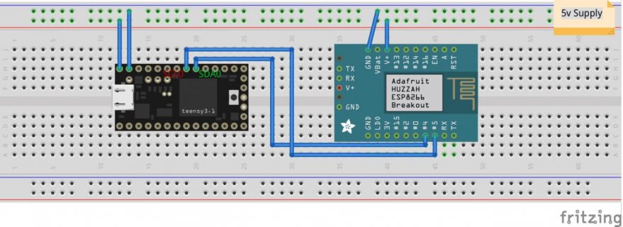
project_breadboard.jpg


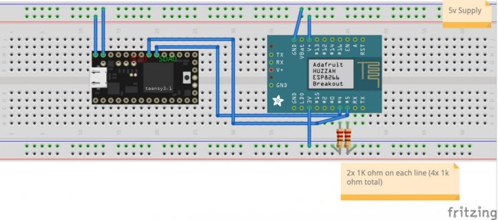
In this configuration I am unable to get the two devices to talk to each other in either master/slave or slave/master configuration. If I set up one as a slave and then use the scanner I get back 0 devices. Curiously, if I replace the Teensy with an Arduino Uno OR I replace the ESP8266 with an Arduino Uno then they are able to communicate without any issues. At this point I feel like it must be related to the logic levels somehow but I'm confused about that.

I know that applying 5v to the Teensy or the ESP8266 can damage them so using the Uno for testing is a bit of a gamble but so far everything has held up ok. I've tried adding pullup resistors to both the SDA and SCL lines (I only had about 4 ~1k on hand so I used two on each without any difference in behavior). I also tried a 10k and that didn't seem to help either (but honestly I don't know enough to confidently say what values I should be using or how to tell if they are working).

I have a logic level converter on hand that I can use if anyone thinks it might help but I'm very confused about why the 3v signals between the Teensy and the ESP8266 wouldn't work on their own. I think since I'm not planning on using an Arduino for this project I shouldn't need to use the logic level shifter at all?


The code I'm using for my tests are just the basic Master_Sender and Slave_Receiver examples from the Wire library, nothing else fancy at the moment. Does anyone have any tips, suggestions or ideas about what I might be doing wrong here? Even just additional thoughts on what I can troubleshoot would be greatly appreciated. Thank you!
 
I imagine you need 2 pull-up resistors on the i2c bus. A pull-up resistor is a resistor that is in parallel to the data path, and goes between the pin and 3.3v. You will need one resistor on the SCL line connecting to 3.3v and one on the SDA line connecting to 3.3v. What value of resistor to use depends on the devices on the bus and the complexity/length of the total wires. A typical value for 3.3v systems is to use 2.2K ohm.
 
This is also something that I tried, but please let me know if it looks like I'm doing it wrong:

project_update.jpg


I don't currently have any 2.2K ohm resistors on hand, if I double up 2x 1K ohm on each line should that be sufficient enough to get something to work? The lines between these devices are less than a foot and I don't intent to have more than 2 Teensy's + 1 ESP8266.
 
In theory it should work (assuming you have the right connection between SCL/SDA and the two machines).

Note, the resistor can be higher than 2.2k. Generally 4.7k is used for 5v systems. Generally, you want it under 10k. However, higher resistors can mean that high speed I2C can be a problem.

Do you have delays in the startup code for both microprocessors. In particular, the Teensy 4.x tends to much faster and can start while the other device may be still initializing.

Have you run Examples -> Wire -> Scanner? If so, does it find the ESP?

Are both i2c sides running at the same speed? Try it at lowest I2C speed.

Generally it can be a good idea to have several LEDs with resistors on each microprocessor. Embedded code to set a particular pin high/low to turn on the light when you get to a state. Or enable the serial console, and print things out (generally if would be helpful to know what the ESP is getting also). That way hopefully you can see where the breakdown occurs.

It may help if you provide the source code for both machines.

Maybe the ESP8266 is drawing too much power. At times it can be useful to have a USB meter that can tell how much power is being drawn. Many USB sources may limit the total power draw to about 500MA for USB systems that don't ask for higher power.

Try running both chips at the slowest possible speed (24Mhz for the Teensy).

Assuming you are using the ESP for networking, make sure that the ESP can actually connect to your wifi devices.
 
Thank you for the extremely thorough response! It is much appreciated! I will try my best to answer each of your questions/troubleshooting tips below:


Note, the resistor can be higher than 2.2k. Generally 4.7k is used for 5v systems. Generally, you want it under 10k. However, higher resistors can mean that high speed I2C can be a problem.

Do you have delays in the startup code for both microprocessors. In particular, the Teensy 4.x tends to much faster and can start while the other device may be still initializing.

I've tried a few second delay, up to 5 seconds for each microprocessor but unfortunately the result is still the same.


Have you run Examples -> Wire -> Scanner? If so, does it find the ESP?

I have tried running the Scanner from the Teensy side and also tried running it from the ESP side and neither one can find the other. I always just end up with "No I2C devices found". However, if I plug the Arduino UNO into the mix they can *both* see the Uno but they can't see each other.


Are both i2c sides running at the same speed? Try it at lowest I2C speed.

Do I need to do anything other than something like this? "Wire.setClock(10000);" Unfortunately this did not seem to make a difference.


Generally it can be a good idea to have several LEDs with resistors on each microprocessor. Embedded code to set a particular pin high/low to turn on the light when you get to a state. Or enable the serial console, and print things out (generally if would be helpful to know what the ESP is getting also). That way hopefully you can see where the breakdown occurs.

The serial console is generally where I've been trying to do my debugging and it has worked fairly well. I'm not sure if there is more that I can be doing to get additional logging from Wire or anything lower level? It really seems like neither device can see each the other yet they can both see an arduino.


It may help if you provide the source code for both machines.

Sure thing! Here is one setup where I have the Teensy running "Scanner" and the ESP as a receiver slave:

Teensy:
Code:
#include <Wire.h>


void setup() {
  delay(5000);
  // uncomment these to use alternate pins
  Wire.setSCL(19);
  Wire.setSDA(18);
  Wire.setClock(10000);
  Wire.begin();
  Serial.begin(9600);
  while (!Serial);        // Leonardo: wait for serial monitor
  Serial.println(F("\nI2C Scanner"));
}


void loop() {
  byte error, address;
  int nDevices;

  Serial.println(F("Scanning..."));

  nDevices = 0;
  for (address = 1; address < 127; address++) {
    // The i2c_scanner uses the return value of
    // the Write.endTransmisstion to see if
    // a device did acknowledge to the address.
    Wire.beginTransmission(address);
    error = Wire.endTransmission();

    if (error == 0) {
      Serial.print(F("Device found at address 0x"));
      if (address < 16) {
        Serial.print("0");
      }
      Serial.print(address,HEX);
      Serial.print("  (");
      printKnownChips(address);
      Serial.println(")");

      nDevices++;
    } else if (error==4) {
      Serial.print(F("Unknown error at address 0x"));
      if (address < 16) {
        Serial.print("0");
      }
      Serial.println(address,HEX);
    }
  }
  if (nDevices == 0) {
    Serial.println(F("No I2C devices found\n"));
  } else {
    Serial.println(F("done\n"));
  }
  delay(5000);           // wait 5 seconds for next scan
}


ESP:
Code:
#include <Wire.h>

void setup() {
  delay(5000);
  Wire.setClock(10000);
  Wire.begin(8);                // join i2c bus with address #8
  Wire.onReceive(receiveEvent); // register event
  Serial.begin(9600);           // start serial for output
}

void loop() {
  delay(100);
}

// function that executes whenever data is received from master
// this function is registered as an event, see setup()
void receiveEvent(int howMany) {
  Serial.println("READING EVENT!");
  while (1 < Wire.available()) { // loop through all but the last
    char c = Wire.read(); // receive byte as a character
    Serial.print(c);         // print the character
  }
  int x = Wire.read();    // receive byte as an integer
  Serial.println(x);         // print the integer
}


I also have a similar configuration in reverse that doesn't really look all that different. When trying an actual sender/receiver pattern I just use the examples straight from the Wire library without any modifications but I can provide those as well if it's helpful.


Maybe the ESP8266 is drawing too much power. At times it can be useful to have a USB meter that can tell how much power is being drawn. Many USB sources may limit the total power draw to about 500MA for USB systems that don't ask for higher power.

This is an interesting thought. I have a super beefy 5v 80amp power supply (40amps) that I tried to hook up as well to rule out power draw as being an issue and it didn't seem to change the result.

Try running both chips at the slowest possible speed (24Mhz for the Teensy).

I've set the Teensy to 24Mhz and the ESP to it's lowest setting (80Mhz) but sadly it still doesn't appear to work. The fact that both devices can see an Arduino hooked up to the bus is extremely confusing to me. It seems to indicate that both devices are functioning properly and *can* work but for some reason they just don't work with each other.

I also tried putting 2k ohm resistors on both lines coming from the Teensy and 1k ohm resistors on both lines coming from the ESP but the result is still the same with neither device being recognized.
 
Hi toddwest,

some remarks:
- Wire.h libs for Teensy4 and esp8266 enable the internal pullup resistors in the chips (Teensy4 22k and esp8266 something between 20k - 50k), so it's good to use an external pullup resistor of 4,7k but nor 2 x 2k (that is much too low). On Teensy4 it depends on the setting of the DSE (Drive Strength Field).
- Wire.h lib for Teensy4 does not support slave mode. An alternative is Richard Gemmells lib, have a look at https://github.com/Richard-Gemmell/teensy4_i2c.
- For Teensy4 Richard and I made the experience that setting the HYS Bit for the SDA and SCL lines gives a more reliable I²C communication. Have a look at this thread https://forum.pjrc.com/threads/57861-I2C-Slave-on-Teensy-4/page2?highlight=Teensy4+i%B2c

Helmut
 
Hi hbit!

I went ahead and grabbed some 4.7k ohm resistors and replaced the 2 x 2k that I had previously. I gave the teensy4_i2c library a shot as well and it works (mostly)!

I took the excellent example code that you provided in that other thread and used the teensy in slave mode and I am able to get pretty decent i2c communication but it seems to fail suddenly with an error at a different point each time. I haven't been able to find any specific pattern to it and I've tried swapping out all of my wiring as well. Sometimes it fails at message 10, sometimes above 80 and sometimes it will run for hundreds of messages without issue.

When it fails, the slave side (Teensy) shows something like:

Code:
# rx: 10 32  tx ok

and the ESP8266 side shows something like:

Code:
tx: x is 194, rx: x is x is x is x is x is x is 193, error_counter: 2 
error_counter: 2, loop_counter: 194

or like this:

Code:
# rx: 9 113  tx ok

Code:
tx: x is 120, rx: x is x iq x is x is x is x is 119, error_counter: 3 
error_counter: 3, loop_counter: 120


Here is the slave code I'm using:

Code:
// Wire Slave Receiver
// by Nicholas Zambetti <http://www.zambetti.com>
// Modified by Richard Gemmell Oct 2019

// Demonstrates use of the Wire library
// Receives data as an I2C/TWI slave device
// Refer to the "Wire Master Writer" example for use with this
// To use it, connect a master to the Teensy on pins 18 and 19.
//
// Consider using the I2CRegisterSlave class instead of Wire to
// create an I2C slave.

// Created 29 March 2006

// This example code is in the public domain.

#include <Arduino.h>
#include <i2c_driver.h>
#include "imx_rt1060/imx_rt1060_i2c_driver.h"


uint8_t number_bytes;
uint8_t i;
uint8_t ii;

const uint16_t slave_address = 0x0055;
I2CSlave& slave = Slave;
void after_receive(int size);
void before_transmit_isr();
void after_transmit();

const size_t slave_rx_buffer_size = 64;
uint8_t slave_rx_buffer[slave_rx_buffer_size] = {};
volatile size_t slave_bytes_received = 0;

// Set up transmit buffer
const size_t slave_tx_buffer_size = 64;
uint8_t slave_tx_buffer[slave_tx_buffer_size] = {};

// Flags for handling callbacks
volatile bool before_transmit_received = false;
volatile bool after_transmit_received = false;
volatile bool buffer_underflow_detected = false;


void setup()
{

  Serial.begin(115200);           // start serial for output
  delay(500);

  Serial.println(" "); Serial.println("I²C Slave Mode Teensy4.0 with lib imx_rt1060_i2c_driver");

  // Configure I2C Slave and Start It
  slave.set_receive_buffer(slave_rx_buffer, slave_rx_buffer_size);
  slave.after_receive(after_receive);

  slave.before_transmit(before_transmit_isr);
  slave.after_transmit(after_transmit);
  slave.set_transmit_buffer(slave_tx_buffer, slave_tx_buffer_size);
  slave.listen(slave_address);

}

void loop()
{
  if (slave_bytes_received) {

    //    Serial.print("loop: slave_bytes_received "); Serial.print(slave_bytes_received);
    //    Serial.print(", last byte transmitted: ");
    Serial.print("# rx: "); Serial.print(slave_bytes_received); Serial.print(" ");
    Serial.print(slave_rx_buffer[slave_bytes_received - 1]); Serial.print(" ");

    // Clear slave_bytes_received to signal that we're ready for another message
    slave_bytes_received = 0;
  }
  if (before_transmit_received) {
    before_transmit_received = false;
  }
  if (after_transmit_received) {
    after_transmit_received = false;
    if (buffer_underflow_detected) {
      Serial.println("App: Buffer Underflow. (Master asked for too many bytes.)");
      buffer_underflow_detected = false;
    } else {
      Serial.println(" tx ok");
    }
  }
}


// Called by the I2C interrupt service routine.
// This method must be as fast as possible.
// Do not perform IO in it.
void after_receive(int size) {
  // This is the only time we can guarantee that the
  // receive buffer is not changing.
  // Copy the content so we can handle it in the main loop.
  if (!slave_bytes_received) {
    slave_bytes_received = size;
    // now copy to transmit buffer
    memcpy(slave_tx_buffer, slave_rx_buffer, slave_bytes_received);
  }
  // else ignore this message because the main loop hasn't
  // handled the previous one yet.
}


// Called by an interrupt service routine.
// This function must be _very_ fast. Avoid IO.
void before_transmit_isr() {
  before_transmit_received = true;
}


// Called by an interrupt service routine.
// This function must be _very_ fast. Avoid IO.
void after_transmit() {
  //    digitalWrite(led, HIGH);       // briefly flash the LED
  after_transmit_received = true;
  if (slave.has_error()) {
    I2CError error = slave.error();
    if (error == I2CError::buffer_underflow) {
      buffer_underflow_detected = true;
    } else {
      Serial.println("Unexpected error");
    }
  }
}


and here is the master code:

Code:
#include <Wire.h>

// define pins for I2C for NodeMCU
#define I2C_PIN_SCL 5
#define I2C_PIN_SDA 4

uint8_t i = 0;
uint8_t ii = 0;
byte buf [64] = {0x78, 0x20, 0x69, 0x73, 0x20, 0x78, 0x20, 0x69, 0x73, 0x20, 0x78, 0x20, 0x69, 0x73, 0x20, 0x78, 0x20, 0x69, 0x73, 0x20, 0x78, 0x20, 0x69, 0x73, 0x20, 0x78, 0x20, 0x69, 0x73, 0x20};
byte *buf_zeiger = &buf[0];
uint32_t error_counter = 0;
uint32_t loop_counter = 0;


void setup() {
  Wire.begin(I2C_PIN_SDA, I2C_PIN_SCL); // join i2c bus (address optional for master)
  Serial.begin(115200);  // start serial for output
  delay(500);

  Serial.println(" "); Serial.println(" "); Serial.println(" ");
  Serial.println("I²C communication test runnig");

}


void loop() {
  Serial.println(" ");
  Serial.print("tx: x is "); Serial.print(i);

  Wire.beginTransmission(0x55); // transmit to device 0x55
  buf[30] = i;
  ii = Wire.write(buf_zeiger, 31);        // sends 31 bytes
  if (ii == 31) {
    // all bytes send
    ii = Wire.endTransmission();    // stop transmitting
    if (ii != 0) error_counter++;
    //  Serial.print(", return value of endTransmission: "); Serial.print(ii);

    i++;

    ii = 0;
    Wire.requestFrom(0x55, 31);    // request 31 bytes from slave device 0x55
    Serial.print(", rx: ");
    while (Wire.available()) { // slave may send less than requested
      char c = Wire.read(); // receive a byte as character
      if (ii < 30) {
        Serial.print(c);         // print the character
        if (c != buf[ii]) error_counter++;
      } else {
        Serial.print(int(c));
        if (c != buf[ii]) error_counter++;
      }
      ii++;
    }
    Serial.print(", error_counter: "); Serial.print(error_counter);
    if (error_counter != 0) {
      Serial.println(" ");
      Serial.print("error_counter: "); Serial.print(error_counter);
      Serial.print(", loop_counter: "); Serial.print(loop_counter);
      while (1) {
        delay(100);
      }
    }
    loop_counter++;
    //  Serial.print(", loop_counter: "); Serial.print(loop_counter);

    delay(150);
  } else {
    // something went wrong
    Wire.endTransmission(); // stop transmission an start again
    Serial.print(" error, # bytes send: "); Serial.print(ii);
  }

}


Any thoughts? I feel like I'm finally super close here! If I can just figure out how to make this communication more reliable I think I should be good to go.
 
Alright, well here is one more thing I just noticed and I hope that someone has an idea of what might be going on here.

Instead of attaching the 4.7k pull-up resistors to 3.3v I attached them to the 5v input instead and now the communication between the devices appears to be perfect. I have been running the test program for 5-10 minutes without a single error. Both the ESP8266 and the Teensy state that 5v should NOT be applied to any pins so I am concerned that this may be causing damage (or has the potential to).

I am just very confused about why this isn't reliable when connected to 3.3v but is when connected via 5v. Anyone have any thoughts?
 
I feel like I'm getting pretty strong evidence here that the ESP8266 is not only 5V tolerant for the SDA/SCL pins (GPIO pin 4 and 5) but that it actually requires 5v pull up to work properly. I had a bidirectional level shifter laying around so I took the SDA & SCL lines from the ESP8266 and ran it through the level shifter to bring it down to 3.3v before sending to the teensy and everything still appears to work perfectly. Edit: Actually, it doesn't work as well as the pure 5v implementation. It failed after ~2000 iterations when using 3.3v to the Teensy.

Has anyone else had this same experience? From every test that I've done it really appears that I2C with the ESP8266 will not function properly when using a 3.3v logic level despite what all of their documentation says ��
 
Last edited:
Hi toddwest,

- 5V ESP8266, there is no need to go to 5V
- my latest test programs follow

ESP8266 master:
Code:
#include <Wire.h>

// define pins for I2C for NodeMCU
#define I2C_PIN_SCL D4
#define I2C_PIN_SDA D3

uint8_t i = 0;
uint8_t ii = 0;
byte buf [64] = {0x78, 0x20, 0x69, 0x73, 0x20, 0x78, 0x20, 0x69, 0x73, 0x20, 0x78, 0x20, 0x69, 0x73, 0x20, 0x78, 0x20, 0x69, 0x73, 0x20, 0x78, 0x20, 0x69, 0x73, 0x20, 0x78, 0x20, 0x69, 0x73, 0x20};
byte *buf_zeiger = &buf[0];
uint32_t error_counter = 0;
uint32_t loop_counter = 0;
String input_string = "";
int number_bytes_tx;
bool string_complete;
char ch;


void setup() {
  Wire.begin(I2C_PIN_SDA, I2C_PIN_SCL); // join i2c bus (address optional for master)
  Serial.begin(115200);  // start serial for output
  delay(500);

  Serial.println(" "); Serial.println(" "); Serial.println(" ");
  Serial.println("I²C communication test runnig");
  Serial.print("input number of bytes for each transmission: ");

  string_complete = false;
  while (!string_complete) {
    while (Serial.available()) {
      // get the new byte:
      char in_char = (char)Serial.read();
      // add it to the inputString:
      input_string += in_char;
      // if the incoming character is a newline, set a flag so the main loop can
      // do something about it:
      if (in_char == '\n') {
        string_complete = true;
      }
    }
  }

  number_bytes_tx = input_string.toInt();
  Serial.println(number_bytes_tx); Serial.println(" ");

}


void loop() {
  Serial.println(" ");
  Serial.print("tx: x is "); Serial.print(i);

  Wire.beginTransmission(0x55); // transmit to device 0x55
  buf[number_bytes_tx - 1] = i;
  ii = Wire.write(buf_zeiger, number_bytes_tx);        // sends x bytes
  if (ii == number_bytes_tx) {
    // all bytes send
    ii = Wire.endTransmission(false);    // stop transmitting
    if (ii != 0) error_counter++;
    //  Serial.print(", return value of endTransmission: "); Serial.print(ii);

    i++;
//    delay(1);
    Wire.requestFrom(0x55, number_bytes_tx);    // request x bytes from slave device 0x55
    Serial.print(", rx: ");
    ii = 0;
    while (Wire.available()) { // slave may send less than requested
      char c = Wire.read(); // receive a byte as character
      if (ii < number_bytes_tx - 1) {
        Serial.print(c);         // print the character
        if (c != buf[ii]) error_counter++;
      } else {
        Serial.print(int(c));
        if (c != buf[ii]) error_counter++;
      }
      ii++;
    }
    //    Serial.print(", # errors: "); Serial.print(error_counter);
    if (error_counter != 0) {
      Serial.println(" ");
      Serial.print("error_counter: "); Serial.print(error_counter);
      Serial.print(", loop_counter: "); Serial.print(loop_counter);
      while (1) {
        if ( Serial.available()) ESP.reset();
        delay(100);
      }
    }
  } else {
    // something went wrong
    Wire.endTransmission(); // stop transmission and start again
    Serial.print(" error, wrong # bytes send: "); Serial.print(ii);
  }

  loop_counter++;
  //  Serial.print(", loop_counter: "); Serial.print(loop_counter);
  if ( Serial.available()) ESP.reset();
  delay(150);
}

Teensy4 slave "Wire" style:

Code:
// Wire Slave Receiver
// by Nicholas Zambetti <http://www.zambetti.com>
// Modified by Richard Gemmell Oct 2019

// Demonstrates use of the Wire library
// Receives data as an I2C/TWI slave device
// Refer to the "Wire Master Writer" example for use with this
// To use it, connect a master to the Teensy on pins 18 and 19.
//
// Consider using the I2CRegisterSlave class instead of Wire to
// create an I2C slave.

// Created 29 March 2006

// This example code is in the public domain.

#include <Arduino.h>
#include <i2c_driver_wire.h>

const size_t slave_rx_buffer_size = 64;
uint8_t slave_rx_buffer[slave_rx_buffer_size] = {};
volatile size_t slave_bytes_rx = 0;
volatile size_t slave_bytes_tx = 0;

// Set up transmit buffer
const size_t slave_tx_buffer_size = 64;
uint8_t slave_tx_buffer[slave_tx_buffer_size] = {};

uint8_t i;
uint8_t ii;
bool state_send = false;

void receiveEvent(int howMany);
void requestEvent();


void setup()
{
  Wire.begin(0x55);               // join i2c bus with address 0x55
  Wire.onReceive(receiveEvent);   // register receive event
  Wire.onRequest(requestEvent);   // register request event
  Serial.begin(115200);           // start serial for output
  delay(500);
  Serial.println(" "); Serial.print("I²C Slave Mode Teensy4.0 with lib i2c_driver_wire");
  Serial.println(" ");
}

void loop()
{
  if (slave_bytes_rx) {

    //    Serial.print("loop: slave_bytes_received "); Serial.print(slave_bytes_received);
    //    Serial.print(", last byte transmitted: ");
    Serial.print("# rx: "); Serial.print(slave_bytes_rx);
    Serial.print("  x is: ");
    Serial.print(slave_rx_buffer[slave_bytes_rx - 1]); Serial.println(" ");

    // Clear slave_bytes_received to signal that we're ready for another message
    slave_bytes_rx = 0;
  }
}

// function that executes whenever data is received from master
// this function is registered as an event, see setup()
void receiveEvent(int howMany)
{
  i = 0;

  while (Wire.available()) { // loop through all but the last
    slave_rx_buffer[i] = Wire.read();       // receive byte as a character
    i++;
  }
  slave_bytes_rx = i;
  slave_bytes_tx = i;
  memcpy(slave_tx_buffer, slave_rx_buffer, slave_bytes_rx);

}

void requestEvent()
{
  
  ii = Wire.write(slave_tx_buffer, slave_bytes_tx);
}


Teensy4 slave "imx_rt1060_i2c_driver" style:

Code:
// Wire Slave Receiver
// by Nicholas Zambetti <http://www.zambetti.com>
// Modified by Richard Gemmell Oct 2019

// Demonstrates use of the Wire library
// Receives data as an I2C/TWI slave device
// Refer to the "Wire Master Writer" example for use with this
// To use it, connect a master to the Teensy on pins 18 and 19.
//
// Consider using the I2CRegisterSlave class instead of Wire to
// create an I2C slave.

// Created 29 March 2006

// This example code is in the public domain.

#include <Arduino.h>
#include <i2c_driver.h>
#include "imx_rt1060/imx_rt1060_i2c_driver.h"


uint8_t number_bytes;
uint8_t i;
uint8_t ii;

const uint16_t slave_address = 0x0055;
I2CSlave& slave = Slave;
void after_receive(int size);
void before_transmit_isr();
void after_transmit();

const size_t slave_rx_buffer_size = 64;
uint8_t slave_rx_buffer[slave_rx_buffer_size] = {};
volatile size_t slave_bytes_received = 0;

// Set up transmit buffer
const size_t slave_tx_buffer_size = 64;
uint8_t slave_tx_buffer[slave_tx_buffer_size] = {};

// Flags for handling callbacks
volatile bool before_transmit_received = false;
volatile bool after_transmit_received = false;
volatile bool buffer_underflow_detected = false;


void setup()
{

  Serial.begin(115200);           // start serial for output
  delay(500);

  Serial.println(" "); Serial.println("I²C Slave Mode Teensy4.0 with lib imx_rt1060_i2c_driver");

  // Configure I2C Slave and Start It
  slave.set_receive_buffer(slave_rx_buffer, slave_rx_buffer_size);
  slave.after_receive(after_receive);

  slave.before_transmit(before_transmit_isr);
  slave.after_transmit(after_transmit);
  slave.set_transmit_buffer(slave_tx_buffer, slave_tx_buffer_size);
  slave.listen(slave_address);

}

void loop()
{
  if (slave_bytes_received) {

    //    Serial.print("loop: slave_bytes_received "); Serial.print(slave_bytes_received);
    //    Serial.print(", last byte transmitted: ");
    Serial.print("# rx: "); Serial.print(slave_bytes_received); Serial.print(" ");
    Serial.print(slave_rx_buffer[slave_bytes_received - 1]); Serial.print(" ");

    // Clear slave_bytes_received to signal that we're ready for another message
    slave_bytes_received = 0;
  }
  if (before_transmit_received) {
    before_transmit_received = false;
  }
  if (after_transmit_received) {
    after_transmit_received = false;
    if (buffer_underflow_detected) {
      Serial.println("App: Buffer Underflow. (Master asked for too many bytes.)");
      buffer_underflow_detected = false;
    } else {
      Serial.println(" tx ok");
    }
  }
}


// Called by the I2C interrupt service routine.
// This method must be as fast as possible.
// Do not perform IO in it.
void after_receive(int size) {
  // This is the only time we can guarantee that the
  // receive buffer is not changing.
  // Copy the content so we can handle it in the main loop.
  if (!slave_bytes_received) {
    slave_bytes_received = size;
    // now copy to transmit buffer
    memcpy(slave_tx_buffer, slave_rx_buffer, slave_bytes_received);
  }
  // else ignore this message because the main loop hasn't
  // handled the previous one yet.
}


// Called by an interrupt service routine.
// This function must be _very_ fast. Avoid IO.
void before_transmit_isr() {
  before_transmit_received = true;
}


// Called by an interrupt service routine.
// This function must be _very_ fast. Avoid IO.
void after_transmit() {
  //    digitalWrite(led, HIGH);       // briefly flash the LED
  after_transmit_received = true;
  if (slave.has_error()) {
    I2CError error = slave.error();
    if (error == I2CError::buffer_underflow) {
      buffer_underflow_detected = true;
    } else {
      Serial.println("Unexpected error");
    }
  }
}

- I found that on Teensy4 side for the pins SDA and SCL in the PAD_CONTROL_CONFIG the IOMUXC_PAD_HYS had to be set, which is done in the latest version of Richard Gemmells lib. The other factor is the setting of the IOMUXC_PAD_DSE (normally set to 4), this is the Drive Strength Field. Have a closer look at the NXP reference manual of the i.MX RT1062. There are example in Richards lib but don' t forget to set IOMUXC_PAD_HYS again.

- For ESP8266 I would use 160MHz or 80MHz clock rate and for Teensy4 600MHz.

I use Teensy4 now in I²C slave mode in this project with communication to a ESP8266. Find ESP8266 code on this site.

Hope this helps,
Helmut
 
Hello Helmut,

Thanks for your reply! Unfortunately, I am not getting the same behavior that you were able to. I am running the latest version of Richard Gemmells lib and also tried both of your teensy slave examples but I continually get an error after 10-20 iterations. I confirmed that I am running the latest version of the library and also tried many different setting overrides using the PAD_CONTROL_CONFIG, nothing seemed to make a difference. Here is what I currently have (which looks like it's the same as the library):

Code:
#define PAD_CONFIG IOMUXC_PAD_DSE(4) | IOMUXC_PAD_SPEED(1) | IOMUXC_PAD_PKE | IOMUXC_PAD_PUE | IOMUXC_PAD_PUS(3) | IOMUXC_PAD_ODE | IOMUXC_PAD_HYS


I have tried DSE from 0 to 6 and it hasn't improved anything. I tried some different pad speeds as well. Using 5V is the only thing that makes a noticeable improvement so I am very confused :(
 
Using 5V is the only thing that makes a noticeable improvement so I am very confused :(
If you are powering the ESP from the Teensy's 3.3v pin, it may be the ESP is drawing too much power.

The 3.3v voltage regulator used in recent Teensies tends to be rated at 250mA (roughly 0.8 watts).

If you are powering the ESP using VIN and the Teensy is plugged into a USB port, you might be able to get 400mA (2 watts) for the ESP.

I recall, one of the reasons Paul changed the voltage regulator in going from the Teensy 3.1 to the 3.2 is to be able to power ESP chips. But the T4 draws more power than the 3.2, so it may be the ESP is just a little power starved. Or possibly something else is using just a little too much energy (i.e. different ESP chip, characteristic of the local wifi environment, etc.).

It may be a useful exercise to measure the total power load (both volts/amps), as well as the power load of just the ESP chip.

Since I had a USB volt/ammeter next to the computer, I measured a few Teensies I had laying around that had my custom blink sketch running:
  • Teensy 4.1 (with psram and 8M flash soldered in): 0.100 - 0.104mA;
  • Teensy 4.0: 0.094 - 0.098mA;
  • Teensy 3.1: 0.034 - 0.039mA.
 
Last edited:
Thank you for all your help and guidance, Michael and Helmut. I think I may have finally found the correct combination to get everything to work properly with 3.3v. I'm not sure exactly what I was doing wrong but I took some time this morning to completely re-write everything from scratch and to clean everything up.

Initially after the re-wire it will still pretty flaky between the devices. I noticed that the only thing I hadn't tried was tying all of the 3v pins together, I had assumed that it was sufficient to use just the 3v pin from the ESP8266 with the pull up resistors since everything else was being powered with my 5v input (I have a separate 5v PSU). Joining all of the 3v pins appears to have solved all of my issues and the communication between each device is flawless.

For posterity here is what my final wiring looks like:

20200607_110255.jpg


Thank you again everyone for all your help. I'm excited to keep moving this project forward!
 
Status
Not open for further replies.
Back
Top