SPI in Registers on Teensy 4.0

Status
Not open for further replies.

Mark_7

Member
Hi everyone,

I'm trying to get better at programming through registers and understanding datasheets. Best way to learn is to practice.
I've challanged myself with getting the SPI working on a teensy 4.0 through direct register manipulation.
I've read the clocking, I/O and SPI chapters of the datasheet and i seem to have everything done. I must be missing a small detail or something because my code doesn't work.

My external sensor that the teensy 4.0 is connected to is an MPU9250. I want to point out that my wiring is correct because i have been able to use the SPI library and get it to work.
To verify that my code is working, i am simply trying to read the WHO_AM_I register.

My code is pretty well commented out (it's a learning project).
Basic Notes:
- I have configured the chip select as a digital i/o pin instead of it being controlled by SPI (i would rather control it through software for versatility)
- LPSPI4 is being used (all the normal teensy 4.0 SPI pins)
- Currently when i read the WHO_AM_I register, i first get 128 and then a whole bunch of 255's...
- SPI should work at 1 MHz
- Not sure how to understand what SCKDIV on page 2952 means.
- Current SPI clock is configured as 664 MHz from PLL3 PFD1 that gets divided by 6 to become 110 MHz. This still needs to drop to 1 MHz.

Any help from somehow who could look over my code and provide suggestions that may get it to work would be great! Code is attached to this post (it's long).

Thanks,
-Mark
 

Attachments

  • main.cpp
    5 KB · Views: 76
Personally for me, I would prefer to see more logical names of registers used then b[n], Yes I could look it up
Instead of:
Code:
	LPSPI4_CR &= ~b[0];				// disable spi1
	LPSPI4_CR = b[1] | b[8] | b[9];				// software reset, reset transmit and receive FIFO
	delay(1);
	LPSPI4_CR = 0;					// turn off software reset
For me it is easier to read:
Code:
	LPSPI4_CR &= ~LPSPI_CR_MEN;				// disable spi1
	LPSPI4_CR = LPSPI_CR_MEN | LPSPI_CR_RRF | LPSPI_CR_RTF];				// software reset, reset transmit and receive FIFO
	delay(1);
	LPSPI4_CR = 0;					// turn off software reset
As mentioned the first thing I would do is hook up Logic Analyzer and see what is going out.

I would check that the IO pins are working properly. If you compare your pin pad setting to SPI library you will see we set them to:
IOMUXC_PAD_DSE(7) | IOMUXC_PAD_SPEED(2)

And depending on which SPI and which IO pins ... You also may need to tell system to select that pin as the input pin for that function...
Look at IOMUXC chapter on settings like: IOMUXC_LPSPI4_SDI_SELECT_INPUT

I don't think these will be problem for default on this one, but on some maybe.
 
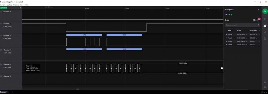
Quick update: It looks like at least some of your stuff is working... At least I can capture SPI output on Logic Analyzer:
screenshot.jpg
 
Hi KurtE,

Well, thanks for doing that. I don't have a Logic Analyzer or oscilloscope (yet)...
I noticed on the SPI SCK signal, it says 499.971 MHz. I'm not fully sure how your tools work, but i'm assuming that is my SPI clock frequency? Clearly that is too high...
If i think about it, you must have some fancy tools to detect such a high frequency and very cleanly...
Maybe the slave (The MPU9250 on my teensy. I'll assume you have nothing connected to your teensy) is not replying because the clock is too fast?

Thanks
 
I ran your sketch with scope and MISO jumpered to MOSI and confirmed it read back what was sent. Scope showed SPI CLK at 8.4 khz which matches your config of CCM_CBCMR, CCS, and TCR, 664.6/6/102/128. Your TCR is set to MODE1 with 128 prescale, you probably want TCR = 7. That will give you MODE0, and SPI CLK will be 1.08 MHz (without 128 prescale). Here are hex values of a few registers of your sketch vs using Teensy SPI lib.
Code:
       LPSPI4_CCR 0xA030064
       LPSPI4_TCR 0x78000007 
       LPSPI4_FCR 0xA000A
       CCM_CBCMR 0xF5AE8104

Teensy SPI lib with SPI CLK 4 MHz, MODE0, 720.3/3/60  = 4 MHz
          LPSPI4_CCR 0x1D1D3A
          LPSPI4_TCR 0x7     
          LPSPI4_FCR 0x0
          CCM_CBCMR 0xE9AE8114
https://github.com/PaulStoffregen/SPI

EDIT: running your sketch at 1.08 MHz (MODE0) with T4 connected to SPI serial flash, I was able to read the flash ID, memory type, and capacity
Code:
LPSPI4_CCR 0xA030064
LPSPI4_TCR 0x7
LPSPI4_FCR 0xA000A
CCM_CBCMR 0xF5AE8104
CCR freq 1.1 MHz
alive
1
20
18
alive
1
20
18
...
 
Last edited:
Hi KurtE,

Well, thanks for doing that. I don't have a Logic Analyzer or oscilloscope (yet)...
I noticed on the SPI SCK signal, it says 499.971 MHz. I'm not fully sure how your tools work, but i'm assuming that is my SPI clock frequency? Clearly that is too high...
If i think about it, you must have some fancy tools to detect such a high frequency and very cleanly...
Maybe the slave (The MPU9250 on my teensy. I'll assume you have nothing connected to your teensy) is not replying because the clock is too fast?

Thanks

You are welcome, @manitou did a much more thorough test than I did, I just hooked up a T4 to Logic Analyzer pins.

And yes I do have a couple of logic analyzers from Saleae: https://www.saleae.com/
These days I seldom debug anything hardware wise without them. Likewise for many software issues as well.
(Sorry for the shameless plug)

I am also using their Alpha or is it now Beta version of their software full rewrite as talked about up at: https://discuss.saleae.com/
 
Hello,

Thank you both for the help. I messed up on the SPI mode and didn't fully understand clocking. The code is now functional.
I have added a couple extra registers I overlooked and cleaned up my code.
I also changed the clock divider's to have more clocking options (about from 1 MHz to 15 MHz)

The current code is configured for Mode 0 and 1 MHz (0.989 MHz to be exact). If one of you can run a logic analyzer and verify the SPI clock speed, that would be awesome!
Hopefully this code will be useful for those trying to understand the Teensy 4.0 I/O and clocking setup for all sorts of modules...

Thanks
 

Attachments

  • SPI4_IN_REGISTERS.cpp
    8.5 KB · Views: 85
You should print out in HEX the registers that affect clock speed, and with the ref manual you could see what values your C code has actually selected.
Code:
        LPSPI4_CCR 0xA030005
        LPSPI4_TCR 0x28000007   
        LPSPI4_FCR 0xA000A
        CCM_CBCMR 0xFDAE8104  clock 0 664.6/8/32/7 = 371 khz
scope on SPI CLK pin also shows 373 kHz

to clear a 3-bit field your mask needs to be 7, should read
Code:
	CCM_CBCMR &= ~(0									// clear the bits for LPSPI related clock stuff						pg. 1110
		| CCM_CBCMR_LPSPI_CLK_SEL(3)
		| CCM_CBCMR_LPSPI_PODF(7)
	);
With that correction you get
Code:
CCM_CBCMR 0xEDAE8104  664.6/4/32/7 742 khz, scope 735 khz
still not the 1 MHz you wanted .... maybe use a TCR prescale of 1 (field val 0) and then CCR of 164. 664.6/4/166 = 1 MHz
Code:
LPSPI4_CCR 0xA0300A4
LPSPI4_TCR 0x7
LPSPI4_FCR 0xA000A
CCM_CBCMR 0xEDAE8104

The Teensy 4 SPI lib uses DMA with the FIFO to get data rates very close to the SPI CLK speed for block transfers.
 
Last edited:
Hi Manitou,

I agree, I missed the mask... That is now fixed.
Also, I improperly setup the CCM_CBCMR[ CCM_CBCMR_LPSPI_PODF(2)] register. Caught that after you wrote
Code:
664.6/4/32/7
But i was trying to do
Code:
664.6/3/32/7


and also printing the register values in hex and going over each one.

The previous code was
Code:
... 
    | CCM_CBCMR_LPSPI_PODF(3)

but the correct version to divide by 3 is actually
Code:
...
    | CCM_CBCMR_LPSPI_PODF(2)

My idea with the way i set up the 3 clock prescalers is to allow flexibility with changing the SPI speeds very easily.
The 664.62 MHz clock gets divided by 3 and 7 (i.e. 664.62 / 3 / 7 ) to give 31.64 MHz. The SPI module can then divide this clock by 32 to get ~1 MHz or it can divide it by 2 to get ~16 MHz. Or about anywhere in the middle.

With those things fixed, my speed test is much more reasonable than before. The speed test results in 50,058 x 2 transactions per second where each transaction is 8 bits long.
That is about 800,928 bits/second and is reasonable for 1 MHz with the chip select controlled through software.
I also removed the extra delays inside the clock configuration register (CCR) since they aren't used.
I think the code should be complete at this point. Of course, if anyone catches something wrong, feel free to correct me, it definitely helps!

Thanks for the help,
-Mark
 

Attachments

  • SPI_IN_REGISTERS_V2.cpp
    8.9 KB · Views: 76
Status
Not open for further replies.
Back
Top