Getting SPI data using Teensy 4.0 and a potentiometer

Status
Not open for further replies.

gc4169

New member
Hi there,

For a project I'm asked to get SPI data from the ADC of a Teensy 4.0 and to display the SPI data in the Arduino debugger. So after a couple of tries I managed to get SPI data varying with the position of the potentiometer, though the variation is not linear.

I get data from the MISO pin (number 12) and data ranges from 0 to 255, and stay at 0 on a great range of the potentiometer. After a slight rotation of the pot, data jumps to 8, after another to 125, then 255, which is the final value till I reach the end of the rotation of the pot. The data seems to jump from one value to another and I want to make this variation linear with the potentiometer. Anyone here would mind help me with that ?

Here is the code I use, anything could be wrong in this since I'm pretty new to the Arduino/Teensy/SPI environment...

Code:
#include <SPI.h>
const int adcCS = 12;
int sensorValue = 0;
void setup() {
  pinMode(adcCS, OUTPUT);
  SPI.begin();
}

void loop() {
  sensorValue = SPI.transfer(adcCS);
  Serial.println(sensorValue);
  delay(10);
}

Thanks a lot :)
 
Sorry, I don't understand your setup and/or what you are fully trying to do.

That is SPI does not typically return ADC data, unless you are connected to some external board/chip which returns Analog data. If this is the case, it might help someone to help you if you mentioned which device you are trying to communicate with and maybe show a picture of your wiring.

With SPI, you will typically need several pins that connect the Teensy to the external board. Often times it will require some voltage and ground pins. Warning the T4 IO pins can only handle up to 3.3v on them, so you need to be careful to make sure that your device does not try to go at a higher voltage, such as 5v which is typical of most of the Arduino AVR based boards like the UNO.

You then typically need some IO pins to connect the two things. Assuming the default SPI object
You need:

SPI Clock: pin 13
MOSI (Master Output this case Teensy to Slave Input in case device): pin 11 - often times you send request out on this
MISO (Master Input Slave Output): pin 12 - This is where the slave device will respond

As SPI can handle more than one device you then typically have a Chip Select PIN.
Often mentioned in Arduino SPI documents, pin 10 is often the default. However with most devices, it can be any digital IO pin.

Also with SPI, there is a clock speed that you often set as part of your code. There are a few different ways. But for new stuff look at SPI.beginTransaction ...

But if you setup where you have the default IO pins mentioned. your code may look more like:

Code:
#include <SPI.h>
const int adcCS = 10;
int sensorValue = 0;
void setup() {
  pinMode(adcCS, OUTPUT);
  digitalWrite(adcCS, HIGH);
  SPI.begin();
}

void loop() {
  digitalWrite(adcCS, LOW);  // lets chip know we are talking to it. 
  sensorValue = SPI.transfer(0);
  digitalWrite(adcCS, HIGH); // we are done talking to it. 
  Serial.println(sensorValue);
  delay(10);
}

But again this may not be fully complete as maybe the device you are talking to needs a command to tell it to send data back, so you may have to transfer that byte (or bytes) first and then do a transfer where you look at the results... But again that all depends on your device
 
On the other hand, if you are just trying to read the potentiometer voltage with the T4 ADC, then all you need to print the voltage is
Code:
void setup() {
}

void loop() {
  Serial.println( 3.3 * analogRead(A0) / 1024);
  delay(1000);
}
The voltage (3.3v or less) from the pot is hooked to A0 (pin14) on the Teensy 4. No SPI needed.
 
Thank you for your answer.

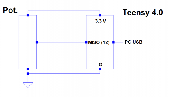
My circuit looks like this, I'm plugging everything on a breadboard :

Teensy pot spi.png

Basically the goal of this manipulation is to make sure that the ADC of Teensy transfers SPI data, and most importantly for me to understand how SPI works. Actually this is only the first step of a bigger forthcoming project, which will consist in transferring SPI data on an FPGA (a Zybo, precisely), using an MCP3008 (which I have at my disposal), and a potentiometer.

Considering KurtE's answer, maybe should I directly use the MCP3008 in the Teensy project, I first thought that the ADC of Teensy would have been sufficient by its own. Also, for pedagogical purposes it was suggested to me to use a code adapted to the MCP3008, used to implement SPI from scratch without using the made-up library : https://github.com/nodesign/MCP3008/blob/master/MCP3008.cpp
 
Sorry this still does not make any sense to me.

SPI or in our case LPSPI - Low Power Serial Peripheral Interface (Chapter 47) in reference PDF again has to do with chips or boards communicating using a serial interface as I mentioned in previous post.

A pot like you show has nothing to do with this. Instead you should use the Analog to Digital Converter (ADC) chapter 65 to convert the Analog data(voltage) to a digital value, as @Manitou mentioned.

Or you can use an external Analog to Digital Converter like the MCP3008(http://ww1.microchip.com/downloads/en/DeviceDoc/21295d.pdf)
Which does the conversion and it uses SPI to communicate with an SPI host such as the Teensy.

And I would not use the library you mentioned as that one appears to do it's own bitbanging of the SPI interface. Instead I would probably either do it myself or probably use one of the Arduino libraries that you can install using the Arduino Tools->Manage Libraries. Example the Adafruit library: https://github.com/adafruit/Adafruit_MCP3008
 
Status
Not open for further replies.
Back
Top