Howdy,
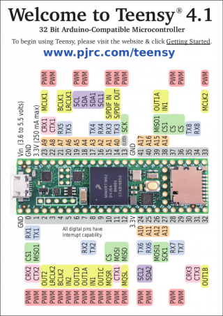
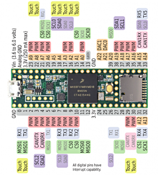
I'm trying to work with the standard SPI.h library and Teensy 4.1. I'd like to be able to use the LED (pin 13) for external signalling at the same time as the SPI interface, but when I use the setSCK() function and try to reassign to pin 27 the clock remains operating on pin 13. My understanding is that setSCK() doesn't work for all pwm pins, but requires an alternative SCK pin as shown on the pinout diagram. But the new 4.1 diagram doesn't seem to have any alternate pins except for those used by SPI1 (they're at least not marked in the same way they were on the 3.5 pinout diagram).
Am I not able to interchange pins between SPI and SPI1? Which pins can I use?


Above you can see how in the 3.5 pinout it shows a faded out SCK0 label on pin 27, but there are no such symbols on the 4.1.
And here is my code. If it helps, I'm using a TLC1543 ADC IC.
Thank you in advance.
I'm trying to work with the standard SPI.h library and Teensy 4.1. I'd like to be able to use the LED (pin 13) for external signalling at the same time as the SPI interface, but when I use the setSCK() function and try to reassign to pin 27 the clock remains operating on pin 13. My understanding is that setSCK() doesn't work for all pwm pins, but requires an alternative SCK pin as shown on the pinout diagram. But the new 4.1 diagram doesn't seem to have any alternate pins except for those used by SPI1 (they're at least not marked in the same way they were on the 3.5 pinout diagram).
Am I not able to interchange pins between SPI and SPI1? Which pins can I use?


Above you can see how in the 3.5 pinout it shows a faded out SCK0 label on pin 27, but there are no such symbols on the 4.1.
And here is my code. If it helps, I'm using a TLC1543 ADC IC.
Code:
// the ADC returns the PREVIOUS conversion result when a transfer occurs.

// the first 4 clock cycles load the address register with input address to select
//  the desired analog channel.
// the next six clocks provide control timing for sampling the analog input.

// MSB of previous conversion appears at DATA OUT on falling edge of CS (1, 3, 5)
//  on the rising edge of EOC (2,4), and following the sixteenth clock falling
//  edge (6). The remaining bits shift out in the next nine clock falling edges.
///////// MSB FIRST //////////


#include <SPI.h>

const int slave1 = 10;
//const int slave2 = 21;

int channels = 14;

void setup() {
  //set slaveSelect pins to output
  pinMode(slave1, OUTPUT);
  digitalWrite(slave1, HIGH);
  //pinMode(slave2, OUTPUT);
  //digitalWrite(slave2, HIGH);

  Serial.begin(115200);

  //initialize SPI
  SPI.setSCK(27);
  SPI.begin();
}

void loop() {

  recordADConSPI(slave1, channels);

}

void recordADConSPI(int CS, int channels){
  Serial.print("\t");
  for(byte chan = 0; chan <= channels; chan++){
    if(chan == 0){
      //First round may not return valid data: returns prev conversion
      //So we preload the ADC with the channel we are interested in
      (GetAnalog(CS, 0));
    }else if(chan == channels){
      Serial.print(chan-1,HEX);
      Serial.print(":");
      Serial.println(GetAnalog(CS, chan));
    }else{
      Serial.print(chan-1,HEX);
      Serial.print(":");
      Serial.print(GetAnalog(CS, chan));
      Serial.print(" ");
    }
  }
}

//x(n) = value of channel n; GetAnalog(CS, n) = x(n-1)
int GetAnalog(int chipSelect, byte address){
  SPI.beginTransaction(SPISettings(2100000, MSBFIRST, SPI_MODE0));
  digitalWrite(chipSelect, LOW);
  word value;
  //SPI.transfer(address);
  value = SPI.transfer16(address<<12);

  digitalWrite(chipSelect, HIGH);
  SPI.endTransaction();
  return value>>5;
}
Thank you in advance.
Last edited:

