Ventialtor for Covid-19 with the Teensy 4.1

Tom1

Member
Dear forum members,

I built a mechanical ventilator powered by Teensy 4.1 for Covid-19 :cool:

IMG_2650_4.jpg


Youtube video:

1.png

Here is some technical details:
http://magicventilator.com/

What you think of it?
 
Magnificent. A remarkable effort and an impressive result.

If you can spare the time, I would love to read about your thoughts and problems as you went through the phases from initial ideas/conceptions to experiment and testing. What is the pressure generator? How is this controlled? Have you tried any failure modes yet, to see what the effects of failures in the system would be?

Are you employed in the bio-engineering industry, or do you fancy a career in that direction?
 
Magnificent. A remarkable effort and an impressive result.
Thanks! :)

If you can spare the time, I would love to read about your thoughts and problems as you went through the phases from initial ideas/conceptions to experiment and testing.
There was many phases. I first tried using a motor and a Bag valve mask like some open source ventilators out there but it didn't seem reliable. Then I bought a few air mattress inflators and found out the AC version was powerful enough for the ventilator.
Then I needed to learn lots of physics like fluid dynamics, thermodynamics and aerodynamics.

I added 2 flow sensors. The flow sensors I'm using are car flow sensors. I needed to learn a lot about flow sensors and how to calibrate them.
I built software for curve fitting to build formulas to translate the flow sensor signals into flow rates.

On the controller side I first I used Arduino Uno as the main controller but eventually I realized that it's too slow to handle so many calculations and control parts so I decided to upgraded to the Teensy 4.1.

For the pressure sensor I'm using the MPX10.
For flow rate calibration I'm using a Pitot tube powered by MPXV7002.

Here is a few links I used for reference:
https://www.instructables.com/id/The-Pandemic-Ventilator/
https://emergency-vent.mit.edu/
https://github.com/jcl5m1/ventilator
https://op-vent.stanford.edu/
PuritanBennett980Ventilator_OperatorsManual_en_US_PT00109658A00.pdf
Design specifications for the Medtronic PB560 ventilator system

What is the pressure generator? How is this controlled? Have you tried any failure modes yet, to see what the effects of failures in the system would be?
Currently I'm using on AC powered mattress inflators. I'm using a triac circuit to control the motor and it's power.
I did many tests like adding different lung simulators with different elastic strength and I also added valves to the output to simulate pinched pipes are a pipe disconnection.
There is a set of alarms you can set that will warn you when something goes wrong.
If for example a pipe gets disconnected the software doesn't have much it can do but just alarm the medical staff.

Are you employed in the bio-engineering industry, or do you fancy a career in that direction?
Currently I don't work at all in the bio-engineering industry but I guess if this ventilator works out I will open a ventilator manufacturing company.

If you have any other questions please let me know!
 
Interesting Tom. I too had considered mattress inflators as a pressure source. You success with flow sensors has my respect. Its a tricky subject.

My point about failure modes is - like software production - probably the hardest nut to crack in production engineering. Any authority (such as the FDA) will not do this for you. You have to show them evidence that you have given this thorough consideration yourself. For example, what would happen if the triac failed short circuit? Would the pump try to blow up the patient lungs like a mattress? Sounding an alarm is not an acceptable solution - could be too late before action is taken. I have a vision of the patient floating away into the distance like some cartoon character :).

Failure mode analysis is important always. But when dealing with patient safety in a hospital environment, it becomes even more so. And this is usually where the costs start to rise.

But these issues are not to distract from your very impressive result. Many great innovators get something "working" first and your video certainly shows this. Well done.
 
Interesting Tom. I too had considered mattress inflators as a pressure source. You success with flow sensors has my respect. Its a tricky subject.
You also tried building your own ventilator? How well it went for you?

Yeah that's true I first tried building my own flow sensor with using a thin copper wire as a hot wire but it was taking too much time and or the copper wire was burning out or the Mosfet controlling the power burned out. Usually for hot wire they use platinum so I decided to just buy a car flow sensor that is like 10 times cheaper than a standard medical flow sensor and I got it to work well.
For calibration I first tried using a digital handheld anemometer but it didn't workout well since when using different size hoses it was giving different results since when they calibrate them they assume an airflow at the full diameter of the anemometer and converting to smaller diameter hoses is not liner. Pitot Tubes really give me good results.

My point about failure modes is - like software production - probably the hardest nut to crack in production engineering. Any authority (such as the FDA) will not do this for you. You have to show them evidence that you have given this thorough consideration yourself. For example, what would happen if the triac failed short circuit? Would the pump try to blow up the patient lungs like a mattress? Sounding an alarm is not an acceptable solution - could be too late before action is taken. I have a vision of the patient floating away into the distance like some cartoon character :).
It's interesting what you said. I agree with you that I need to create a document with many details of types of failures and how MagicVentilator will recover from it.
It seems to me there is 2 types of failure. (1) A failure that can be handled and have some path of recovery for example if the patients lungs get stiffer and the flow rate goes down then we can increase the pressure and push in more air (2) Failure with no way to recover like if a hose gets disconnected then in that case there is nothing that the ventilator can do aside from turning on an alarm and shutting off the air flow.

For over pressure I added a mechanic popup valve that if the pressure passes 60 cmH2O the popup valve will activate and release the pressure.

For failed triac for example the Inspiratory/expoiratory valves also control the flow and with the popup valve it should never reach a fatal pressure to the patient.

Failure mode analysis is important always. But when dealing with patient safety in a hospital environment, it becomes even more so. And this is usually where the costs start to rise.
That's true especially with parts more reliable parts are usually more expensive.

But these issues are not to distract from your very impressive result. Many great innovators get something "working" first and your video certainly shows this. Well done.
Thanks!! :)
 
How the Magic Ventilator works

Main-Diagram_3-1024x593.jpg


Here are the basic parts I used:
  1. AC powered Air mattress inflator (120v or 220v depending on what country you are in).
  2. x2 car mass flow sensors with flow temperature sensors.
  3. x2 DC Direct acting solenoid valves (0-5psi).
  4. Pressure sensor (I used MPX10).
  5. Pressure relief valve (Can be made from parts bought from a local hardware store (Please contact me for details).
  6. x2 HEPA filter.
  7. 3/4 inch plumbing pipes (Can be bought from any local plumbing store).
  8. Arduino based micro controller (ESP32 or Teensy). Arduino Uno is not fast enough to handle it.
  9. Power supply with x3 LM317T to match to the different voltages needed by the different components.

Basic circuit diagram
Circuit-Diagram_1.jpg


Basic description of how it works
  1. During inspiratory phase we control the AC air pump with the triac and pump in air at certain speed and pressure.
  2. We open the inspiratory solenoid valve and let the air flow through the air flow sensor and through the HEPA filter and into the patient lungs.
  3. Once inspratory phase is over (can be triggered by time, volume or pressure) we open the expiratory solenoid valve and release the air through the expiratory flow sensor and out through the expiratory HEPA filter.


Some details of the circuit

AC_Control-2048x1034.jpg

AC control circuit (120v – 220v) for the air pump

MOSFET.jpg

Solenoid control circuit. I used 12v solenoid but modified it to use 5v since breathing pressure is not high (never exceeds 1 psi).

Calibration tools
Low Pressure Gauge (1 psi or 30 inch of water is enough) to add to the ventilator when testing to make sure you have the pressure reading correct.
Pitot tube to calibrate the flow sensor (Pitot tubes are used on plans and boats to measure their speed).

User interface and software
I’m using a python server to run locally on a laptop and communicate with the ventilator hardware.

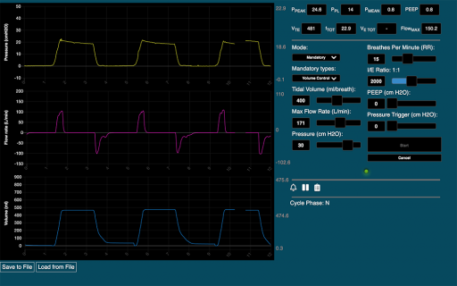
The user interface runs on a Chrome browser and communicates with the python server to send user command to the hardware and to display to the user graphs, alarms and the ventilator status.
 
Back
Top