Wishlist: Card updates for T4 and T4.1

KurtE

Senior Member+
@Paul (and Others) - Not sure if this is the best place or way to suggest things that would be nice to see updated on the T4 and T4.1 pinout cards: (https://www.pjrc.com/teensy/pinout.html)
Would be great if for the cards that actually ship with new boards, but in the mean time it would be good to at least have the information up on the web page.

T4 - I wish pins 0 and 1 were updated to show the SPI 1 pins:
Again not the greatest edit:
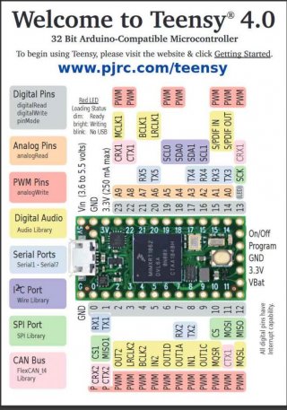
T4-Card-Front.jpg

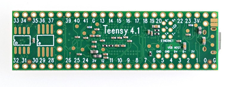
T4.1 - Obviously documentation on the bottom pins would be great:
Somethings for the front of the card:

Pin 39 - MISO1 - Currently in SPI library pin 1 is default for this, so probably should be in the font color that says this.

SPI CS pins - Not sure (actually for T3.x as well) what is the best way to document these? Note: I wish that general SPI documentation would mention that for most cases when you are the SPI master device, the hardware CS pins only mater if you are using a special driver that makes use of the hardware CS...

But back to this. The T4.x SPI CS pins are very different than T3.x SPI CS pins. In particular with T3.x the PUSHR register has a bitmask of which SPI CS pins (potentially more than 1) that should be updated by the transfer. Whereas with the T4.x the TCR register can specify which one of the hardware CS pins is used by index (singular).

In both cases there may be more than one physical pin that maps to the same hardware CS signal. I believe that for slave mode, that on T4.x, you can choose which of the PCS signals to use, whereas on T3.x I believe that you can only use PCS0...

The reason I mention these is with the T4.1 there are both types shown on the card.
That is for SPI: it shows pins: 10, 36, 37 - Which are all unique PCS values.

But for SPI1: you have pins: 0, 38 and both are PCS0 - But again this is only important if you have two things trying to use both of these as hardware CS pins...

For back of card:
Show the 5 signals, VBAT... ON/OFF
USB Host pins
memory chips
Ethernet
USB signal pogo pin location.

I am guessing SDIO pins may not make the cut, but :D

I know my own Excel does not show all of the information, but currently looks like:
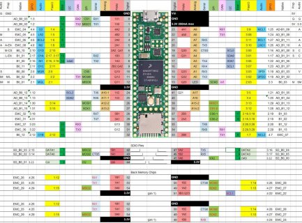
T4.1-Cardlike.jpg

Thanks
Kurt
P.S. - Hope things are going well for all of you!
 
It would be nice to indicate in some what which pins are used by the rev. D audio shield.
 
It would be nice to indicate in some what which pins are used by the rev. D audio shield.

Getting a CARD with each Teensy is Awesome - so nice to have a ready reference for pin functions. Getting any other 'Arduino' ready device and no card makes them harder to confirm function and use.

Would be just as nice for Audio board to get upgraded to include a Card:: Rev C on one side and Rev D on the other or Pinout for both on front and essential ref on the back. But merging that onto already crowded Teensy card would likely cheat more users that it would help.

The 'void' on the T_4.1 card backside will be nice when filled. Many user questions not knowing what is where - even knowing it is nice to have it as full color reference.
 
@MarkT - These cards are always a trade off, of how much data can put on them that help the most people without making it confusing for others. So far the main stuff in the first post of this thread is to suggestion some fixes to the existing T4 card and stuff to complete the T4.1 card.

As @defragster mentioned, potentially the Audio boards should come with a datasheet that shows which pins they use. You can find all of the data for them up on their product page:
https://www.pjrc.com/store/teensy3_audio.html

Sorry, slightly off my own topic:
I actually wish there would be 2 or 3 different official versions, probably also with more details up on main product page and/or WIKI.

For simple things like, what pins are the TX, RX pin for Serial3 on the T4.1, I will simply look at the simple card.
For most other things I usually have my excel document open.

The difficulty for Paul is limited space, plus too much data overwhelms, and each of us may want/need different subsystems and maybe different levels of data for each.
For example for me on a smaller card, I would rather see data about (FlexIO, XBar, GPIO port/pin, Native pin name) over seeing information about Audio and CAN,
and either save space by Reducing PWM to either just P, or Just a Pink bar on the pin number OR use the room to show Timer information, such that you can look at the document and for those who wish to change the PWM frequency why for example changing the frequency for pin 2 also changes it for pin 3... But then again my interests and priorities are probably very different than others.

Sorry again for the diversion.
 
You know, I'd be happy to try and whip up an example interactive page (client-side/browser only, will work fine even if saved as a local file) to show the different options, with tooltips/rollovers and highlights for the various pins. Allowing enabling/disabling/highlighting different operations would definitely reduce clutter.

These things are often very much "write-only" (worse than spaghetti), but I have an idea on how to make the JavaScript needed easier to maintain. (Obviously, the same should work for all Teensies.)

If you have ideas, let me know; otherwise, I'll report back to this thread if I get something sane cobbled together.
 
I was too lazy to add more than the GND and SPI1 pins, but at least you can see how this would work.
I rotated https://forum.pjrc.com/teensy41_2.jpg, cropped it, and saved as a 199×704 pixel JPEG image as teensy41_back.jpg.
teensy41_back.jpg
Everything interesting happens in teensy41_pins.html (rename from View attachment teensy41_pins.txt).

Near the top, you can see a JavaScript pins array. It defines each pin as a circular region on top of the SVG image. For now, only on the backside (center and radius), with the tooltip.

Another array, groups, defines selectable pin groups. Each group produces a clickable button (first click shows, second hides).

Pins belonging to a group are defined by name, and multiple pins can have the same name.

Now, I am not an UX specialist, and this is not the best way to present information, but we could easily add text fields and such in the arrays, even modifying the tooltip as necessary.
The key point here is the Javascript arrays. I used Inkscape (with 1:1 scaling) to find the circle coordinates (and chose radius 10 for all, because it seemed to work), and that as the one annoying part doing this.

I would like to know your opinion whether that array mechanism is maintainable, and whether it works in your browsers. (I use Firefox on Linux.)

Visually, there are no limits. For example, we can create a row of text elements on each side of the SVG image, with pin labels that can be enabled/disabled just like the pin groups. (The labels can either flow towards the image, or stay put.) I personally would like to add not just all pin roles, but also the schematic pin labels and the GPIO bank addresses.
(For example, we can give each pin group their own color, and blend the color in Lab color space when a pin is enabled by more than one group. If we have a table of pins, we can use rollover on the table entries to highlight that particular pin, and so on.)

Are there any really high-resolution images of the Teensy 4.1 that can be put on a web page like that? The 704-pixel tall JPEG isn't horrible, but I'd prefer a resolution twice that. Locating the pins and pads (using more than one circle for the same pad) is the annoying part of the job, so I'd like to do that only once for better/more scaleable JPEG images.

@Paul: I consider these copyrighted by you/PJRC.com. I like your work, and just thought I would suggest this, in case it is something you would consider adding somewhere for us Teensy users to use. The cards are nice, but an interactive web page can save a lot of time looking for individual pins.
 
Does anyone have higher-resolution front and back images of Teensy 4.1? I don't have one (yet), so I can't take my own pics either.
I'd like to crop/rotate/scale them so that they match, and make the board image in the center flippable, so the long side should be say around 2000 pixels.
(If I start with smaller images, they easily get annoyingly mushy.)
 
I know, defragster; the issue is that it is slightly different size to the back one, so swapping them in place creates a jarring "jump" effect.
I'd like big enough pictures I could rotate and scale to same size, so the "turn" would feel natural. (Can put animation in place, too.) Re-editing these blurs them annoyingly.
A final size of 700 - 1000 pixels suffices, but if it was twice that, it would look really sharp on HiDPI displays, and in case users have the screen estate. And, as a rule of thumb, you'll want about twice the resolution or more for masters to not get any blurring due to rotation/scaling.

The JPEG image is linked from within the SVG, and the SVG itself scales naturally to its container, so I'd like to keep it screen resolution independent.
 
They are oriented as flipped with micro USB - it has to flip on some axis?

Size off some by amount of crop/white space diff.

Open that image in browser and zoom to 500% and it doesn't get mushed at all.

t41bz.png
 
cropped the white space - still offset with USB on one end but not the other - then grew the back image up to the same 750 pixel width.
teensy41_4.jpg
teensy41_2.jpg

With white space on ends opposite the USB it wouldn't shift.
 
I mean, if I add a button that changes the side of the board shown –– and yes, pin positions will change, and effectively left and right side labels etc. swap places –– the image jumps, because the images of the boards are different sizes.

The files are in JPEG format, with quality 88. If I resize and finesse the images, then the quality drops because of recompression. I can't even add whitespace around the images because that too recompresses (requantizes) the image.

Note that this is different than resizing the images in the browser, because the browser does not need to recompress the rescaled version.

The only real way would be to define each board side a different rectangle in the SVG image (because that matches how browsers resize the image on-screen), but I'd really, really prefer to just edit better versions for high-res originals.
 
I saved them at highest quaility after edit - can't restore jpeggery - but they double++'d in size.

Paul had those in great light and mostly square when I cropped them - not sure a better image exists.
 
combined in one in mspaint and shifted USB offset and got the same size - lost some quality on save - but photoshop again too much for now.

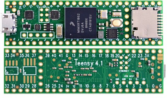
teensy41_both.jpg

I can save as SVG - but not sure of the params and if that helps from prior images.
 
combined in one in mspaint and shifted USB offset and got the same size - lost some quality on save - but photoshop again too much for now.

View attachment 20993

I can save as SVG - but not sure of the params and if that helps from prior images.
I would flip the back image the other way around, even if Teensy 4.1 is written upside down
 
I would flip the back image the other way around, even if Teensy 4.1 is written upside down

Yeah - rotating the Bottom image easy - having the USB header same end gives a better reference than the text.

@KurtE - that rPi interactive and info is very good and complete.
 
Here's what I meant: View attachment teensy41-sides.txt saved as teensy-sides.html .
(I realized I could make the SVG canvas a standard size, and reference the pin locations to that, then scale and rotate the JPEG images to match, using the original images (literally, linking to) https://forum.pjrc.com/teensy41_2.jpg and https://forum.pjrc.com/teensy41_4.jpg .)

Pressing the "Turn" button will show the other side. Only one side is shown at once. It is not a problem that the pin locations change based on which side is shown.
To also test another aspect, this one will autoscale to full browser window size.

I'm thinking of making the Teensy image 24 label rows high, with zoom buttons to adjust scaling (but obviously your browser can also do that, usually Ctrl+scroll wheel). For usability, the +/- zoom buttons and maybe even a settable zoom percent scale may be useful. For example, when using a laptop, I can use Ctrl + and Ctrl -, but optimum scaling often is between the steps. Similarly for when using a tablet.

(Just think of having the page open in a vertical tablet, and poking your finger to check you're connecting a wire to the correct pin. It'd be nice, I think.)

I'm definitely not giving up on this; the 'Pi display is along the same lines, but think about if you could choose which type of information is shown: SPI, I2C, etc.; GPIO bank and bit; schematic pin label; and so on.

I wish I had my old teammates, a graphic artist that understood the importance of user interaction, and a digital media specialist, to help! :)

Oh, I forgot to ask: I could put these at https://www.nominal-animal.net/teensy41/ for much easier testing, temporarily, unless Paul Stoffregen or anyone else objects?
 
Those examples and images look good for a promising future. Did you find better images or are those the ones PJRC provided?
Given screen size having both in view at once could be nice - perhaps only animate the one swapped closest to any defining text?
In the end when multiple items are selected conflict on a pin it might get a unique (red) color?

Feature Creep?: Will it allow clicking each GPIO pin and marking it as used and perhaps a 'comment' for usage that could pop up in a pin list.
 
Did you find better images or are those the ones PJRC provided?
Those are literally the same images; teensy41-sides.html links to the ones hosted here.

Given screen size having both in view at once could be nice
True. I was thinking of the case when considering a pin on one side, and having to connect it from the other side, but actually, we can just avoid that by having a rollover/click highlight the same pin on both board images. Yes, I think that is a better approach than turning the board.

In the end when multiple items are selected conflict on a pin it might get a unique (red) color?
Another good suggestion, methinks. Color coding, or perhaps a circle; or maybe a gentle slow pulsing, although animation can look bad on really slow machines, like low-powered Linux/Android tablets. (Hard blinking annoys me too much for me to do that.)

Feature Creep?: Will it allow clicking each GPIO pin and marking it as used and perhaps a 'comment' for usage that could pop up in a pin list.
At this point, we need to consider all possible features, since later, it is easier to drop features than add them in, so no Feature Creep yet. And yes, that definitely is a good idea, and not at all difficult to implement.

I like the way you're thinking about this, as a tool to help with design/experimenting, choosing the pins to use for a project. That's my core need for myself.

We could have a separate "spreadsheet" lower down, with user-fillable custom labels and descriptions for pins. (Although I could put them as separate pages, I'm not sure if current/future browser protections would allow them to pass content between each other.)
The labels could also be shown next to the pins as one group/type, with descriptions as tooltips, for example. The labels can be editable in both places (I've always liked DHTML and WYSIWYG :)), and edits in one will reflect on the other. When editing one in the "spreadsheet", that pin could be highlighted in the board image.

Now, I'll need to look at the existing cards and spreadsheets, to steal the pin groups/types from those, and see how best to show them next to the board images. I'm thinking the buttons need a dual role: one that shows/hides pin type labels on the sides of the boards, and another that "marks" or labels the pins somehow.

I'm hoping to get more ideas on functionality, especially so if stemming from actual experience when working with projects. I've done so few I cannot rely just on my own. Any further ideas are appreciated!
 
Back
Top