Burnt IC question

Status
Not open for further replies.

siri

Member
Hello!

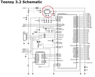
I have a teensy 3.2 on this kind of board (https://www.digikey.com/en/maker/pr...hookup-guide/240cb1e2abe74be0bf07ff6bb3ef5e1f) and this IC (see circle) Screenshot_2020-07-18_22-52-30.png
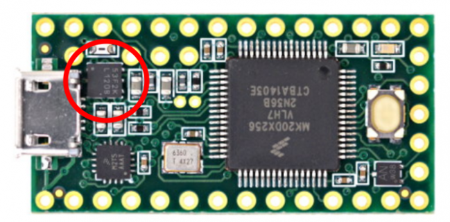
caught on fire.

What is this IC? I couldn't find this information, and I need to know in order to find the cause of the problem.

Thanks for your help,

Best,

Gregory
 
The chip is an LP38691 low drop regulator supplying 3V3 to the board:

T32.png

This regulator is supposed to have Thermal Overload Protection so catching fire is...interesting?
Perhaps a higher external voltage was put on the 3V3 pin?

Paul
 
Hi Paul, thank you for your answer!

If that pin gets shorted to ground, could that make it catch fire?

Also, when we talk about 3.3V pin, we are talking about the one next to pin 23 and not the one next to pin Vbat, correct?

Thanks,

Gregory
 
And 3rd question, that 3.3v pin next to Vbat, would it whistand better a short circuit in between the 3.3v and Ground?

There is a cable with 3 wires, one connected to GND, one to 3.3V, one to an I/O pin and it connects to a sensor using a 1/8” jack. I suspect if the jack is not fully inserted or if they insert it when the device is already powered on (or if some wires are twisted inside the female jack barrel) the tip get shorted to ground and it could cause the IC to catch fire.
 
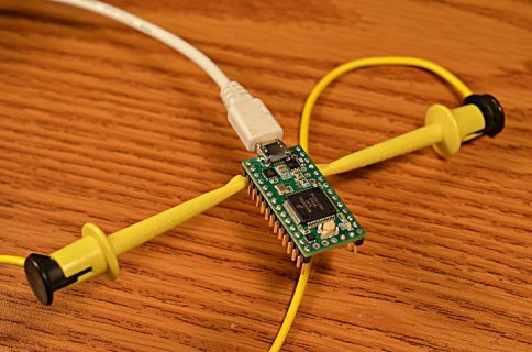
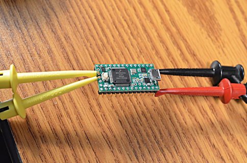
As a quick test, I intentionally shorted 3.3V to GND. The chip gets very hot, but does not catch on fire.

DSC_0930_web.jpg

When I remove the wire, the board continues working.
 
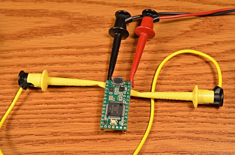
For a second test, I connected the Teensy 3.2 to a BK Precision 1747 power supply, which can source up to 10 amps.

DSC_0931_web.jpg

Again, the chip gets very hot but does not catch on fire. When I remove the yellow wire, the Teensy 3.2 begins running again.

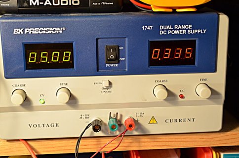
I repeated the test several times. When I connect the yellow wire, the current start around 0.5 amp but quickly decreases (probably in response to the chip getting hot) until it reaches about 0.35 amp and then continues slowly decreasing until about 0.28 amp.

DSC_0932_web.jpg

I did a test where the left the short in place for well over a minute. Again, the moment I remove the yellow wire, that Teensy 3.2 begins running again.
 
To specifically answer your 3 questions....

If that pin gets shorted to ground, could that make it catch fire?

No. As you can see in the photos, I tested here. The chip does not catch fire, even with used with a power supply which could source 10 amps. The thermal regulation inside the chip appears to be working quite well.


Also, when we talk about 3.3V pin, we are talking about the one next to pin 23 and not the one next to pin Vbat, correct?

As you can see in the photos, I tested shorting the 3.3V pin near the regulator to the GND pin next to pin 0.

Because you asked, I repeated the short test several times using various combinations of the 3.3V pin and GND pin on the right hand side, and even the USB connector shell.

DSC_0933_web.jpg

I got the same result every time. No burning. Approx 0.5 amp that quickly decreases to about 0.35 amp, then continues slowly going down. Every time the Teensy 3.2 you see in these photos did the same thing. The chip never burned. Every time I removed the short, it worked again. In fact, it's still blinking right now as I type this message.


And 3rd question, that 3.3v pin next to Vbat, would it whistand better a short circuit in between the 3.3v and Ground?

There is no significant difference. I specifically tested shorting those pins. It does the exact same thing. Well, att least as "exact" as can be observed by watching the BK Precision 1747 current reading.
 
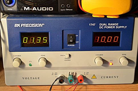
For 1 final test, I checked to make sure my power supply really can deliver 10 amps into a short (that the lack of burning or damage was not due to limited capability of the power supply or inability of the wires to conduct large current)

This test is with the "mini grabber" wires clipped together. The 1.35 volt reading would suggest the total resistance of those wires & clips is about 0.135 ohms.

DSC_0934_web.jpg

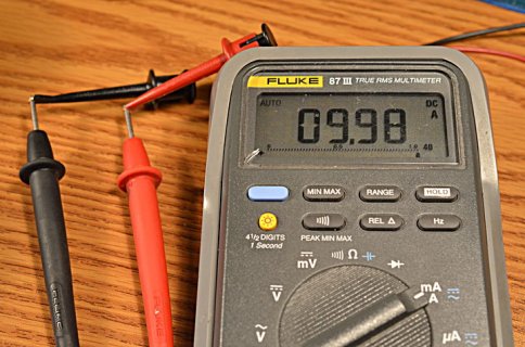
Just to confirm the current really is 10 amps, I also connected the power supply output to a Fluke 87 multimeter.

DSC_0935_web.jpg

During these 10 amp tests, the wires do noticeable warm up!
 
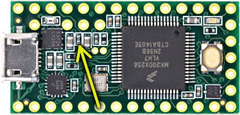
Having focused so much on the voltage regulator, I should mention there is a way to easily burn this ferrite bead inductor which is near the regulator.

teensy32.jpg

If 5V is shorted to AGND, a very large current will flow through that part and cause it to overheat or burn, depending on how much current the 5V power source can supply.

But that part is pretty visually distinct from the regulator.
 
Hi Paul, thank you very much for the quick follow up, it is very appreciated, especially as I only have today to fix that thing.

Here is a picture of the chip : https://imgur.com/a/rBrsuRb

I’ll keep on troubleshooting, if something rings a bell, let me know.

Thanks again for your help,

Best,

Gregory

Btw : this has been done on two devices, both being connected to a ultrasonic sensor via the 3.3v pin next to GND, GND and an I/O pin. A 5V regulator is giving power to Vin and connected to ground. All this via this red board i posted earlier, and an audio shield on top of the teensy. The client has more of those that are functioning fine, the only difference on those two new sets are that instead of powering the sensor from the 3.3v next to Vbat i powered it from the one next to gnd. And instead of using 3.3v external regulator to feed the teensy i used a 5v. The sensor is a 7070 maxbotics. There is a lot of connectors and wiring, maybe that’s where the problem lies.
 
Perhaps someone connected the 5V power wires backwards? That's pretty much never an issue with USB, since the connector won't fit backwards. But if you're using a connector which can be plugged in the wrong way, or a human is just connecting the wires and could get them mixed up, maybe that could be the cause?
 
Perhaps someone connected the 5V power wires backwards? That's pretty much never an issue with USB, since the connector won't fit backwards. But if you're using a connector which can be plugged in the wrong way, or a human is just connecting the wires and could get them mixed up, maybe that could be the cause?

Hi Paul,

In the end I just replaced everything with old sets and it's working fine. I have no idea what was the cause of the problem.

Thanks anyway for your fast help, this was really appreciated.

All the best,

Gregory
 
Status
Not open for further replies.
Back
Top