I2C between Teensy 3.6 and AM4096 encoder: I cannot find the right packet format!

Status
Not open for further replies.

RRdae

Active member
I am trying to create a library to enable communication between a Teensy 3.6 (master) and an AM4096 encoder (slave). The encoder requires interfacing over I2C to adjust settings before it can be accessed over SPI. So far, I have been able to get the encoder to acknowledge, but every attempt I have made to access either the EEPROM or registers over I2C ends in a NACK error. The encoder specifies that it utilizes clock stretching when accessing the EEPROM, but not for accessing the registers (trying to access either one ends in the same NACK error). Can anyone offer advice on this?

Datasheet available here:
https://www.rls.si/eng/am4096-12-bit-rotary-magnetic-encoder-chip

This is the code I am trying to use to read the register. Note that the encoder uses 16bit registers. This particular bit of code I borrowed from another I2C sensor, so I know it is functional. Here I2C_WIRE=0, i2c_address=0, and adc_command=0-55 (I think, but the manual references an 8 bit code for this value, but gives no further details).
Code:
int8_t AM4096::AM4096_read_16_bits(uint8_t adc_command, uint16_t *adc_code)
// The function returns the state of the acknowledge bit after the I2C address write. 0=acknowledge, 1=no acknowledge.
{
    int8_t ack;

    union
    {
        uint8_t b[2];
        uint16_t w;
    } data;

    // ack = i2c_read_word_data(i2c_address, adc_command, *adc_code);

    if(I2C_WIRE == 0){
        Wire.beginTransmission(I2C_ADDRESS);
        Wire.write(adc_command);

        ack = Wire.endTransmission(false);

        Wire.requestFrom(I2C_ADDRESS, (uint8_t)2);

        data.b[1] = Wire.read();
        data.b[0] = Wire.read();
        
    }else if(I2C_WIRE == 1){
        Wire1.beginTransmission(I2C_ADDRESS);
        Wire1.write(adc_command);

        ack = Wire1.endTransmission(false);

        Wire1.requestFrom(I2C_ADDRESS, (uint8_t)2);

        data.b[1] = Wire1.read();
        data.b[0] = Wire1.read();
    }else if(I2C_WIRE == 2){
        Wire2.beginTransmission(I2C_ADDRESS);
        Wire2.write(adc_command);

        ack = Wire2.endTransmission(false);

        Wire2.requestFrom(I2C_ADDRESS, (uint8_t)2);

        data.b[1] = Wire2.read();
        data.b[0] = Wire2.read();
    }else if(I2C_WIRE == 3){
        Wire3.beginTransmission(I2C_ADDRESS);
        Wire3.write(adc_command);

        ack = Wire3.endTransmission(false);

        Wire3.requestFrom(I2C_ADDRESS, (uint8_t)2);

        data.b[1] = Wire3.read();
        data.b[0] = Wire3.read();
    }

    *adc_code = data.w;

    return ack;
}

This is a ping function that I run alongside the above function. It consistently returns 0 (good), where as the first fails (NACK) as soon as adc_command is sent over I2C.
Code:
byte AM4096::Ping()
{
    Wire.beginTransmission(I2C_ADDRESS);
    byte error = Wire.endTransmission();

    return error;
}
 
After Wire.requestFrom(), perhaps call Wire.available() to check whether 2 bytes really are available in the Wire library buffer.
 
Thank you for responding Paul!

I added Wire.available() after the requestFrom and it shows that 2 bytes are available, but all it returns is 11111111 11111111. The problem seems to be when I try to tell the AM4096 which register I want to read via
Code:
Wire.write(adc_command);
because ACK always returns 3 when I write adc_command.
Code:
        Wire.beginTransmission(I2C_ADDRESS);
        Wire.write(adc_command);

        [B]ack[/B] = Wire.endTransmission(false);

        Wire.requestFrom(I2C_ADDRESS, (uint8_t)2)
 
The scanner says that a device was found at address 0, which is the correct default address for that encoder. Could the address being 0 be causing issues?
 
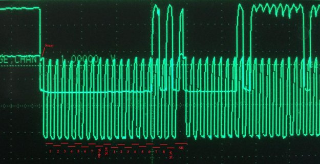
I put my scope on the SDA & SCL lines. It looks like the second ACK is failing for some reason. This is with the following code:

Code:
        Wire.beginTransmission(0);
        Wire.write(2);

        ack = Wire.endTransmission(I2C_NOSTOP);

        Wire.requestFrom(0, (uint8_t)2);

        data.b[1] = Wire.read();
        data.b[0] = Wire.read();

image1(7).jpg
 
Addresses 0 to 7 are supposed to be broadcast addresses which all I2C chips hear. So if you have any other I2C devices connected, I would imagine address 0 could cause issues.

I'm also struggling to understand this:

The scanner says that a device was found at address 0,

Maybe you modified the Scanner example? The code as published starts with address 1.

Use of address 0 is very unusual. It might be a problem, but I honestly just do not know for sure. Is there any way to get this chip to use a normal I2C address (8 to 127 is the normal range).
 
I'm also struggling to understand this:

Sorry. Yes, I had to make a minor change to the Scanner, changing the For loop to start from 0 instead of 1 so that it would pick up the default address of the encoder.

Right now there are no other I2C devices on the wire. It is strictly the encoder demo board w/onboard pullups and a Teensy 3.6. The I2C address can be programmed, but I would need to be able to read/write to the encoder over I2C to do so, just a teensy bit ironic if the default address is what is preventing R/W.

Example code for this encoder is also extremely scarce, but I did find one small library on Github. His I2C read/write program sections are identical to mine, but he used an Arduino uC. I may break out one of my old 2560's and try his code. Maybe there is some combination of hardware happening here that the encoder just is not liking.

I was looking closer at the scope traces and noticed that where it should be a "Repeated Start" during the CLK gap in the middle of the image it looks like what may be actually occurring is a "Stop" followed by a "Start". Do you know if the i2c_t3 library or the original wire library is able to handle "Repeated Start"s?
 
I contacted RLS and their response to my query as to why the encoder is NACK for all possible EEPROM or Register addresses was "I do not know. Our programmer connects fine."

I have checked every bit of the I2C phrase with my scope and what the Teensy passes to the encoder looks correct by both normal I2C convention and the convention described in the encoder manual. I am confident to say that the issue lies not with the Teensy, but with the encoder. At this point, I am abandoning this encoder in favor of the AS5147.

Paul, Thank you for responding and offering advice. I really appreciate it!
 
Status
Not open for further replies.
Back
Top