virtualdave
Well-known member
Hi all,
Feeling pretty noobish with this question. Clearly showing my lack of solid electronics education here
Building a controller board for an arcade cabinet with teensy 3.2 as the brains. Controls LED's, monitors coin drops, allows clients to make settings via a buttons and a pop-up UI in the game software, and so on. It also spits out tickets, and this is where I need help.
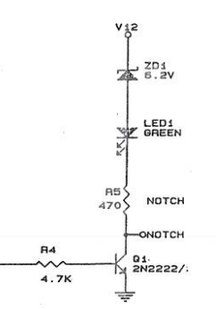
Two wires. One is the enable wire, where anything over 2V turns on the motor to dispense tickets. The other is an input from the ticket dispenser to the teensy. It goes low every time it detects a notch in the ticket (a little light sensor that senses when that little half circle notch in the corner of the ticket passes over). Using the wires together you deliver and count tickets. The unit is powered by 12V DC. My current head scratching comes from the notch sensor. In the docs (for both of the most commonly use ticket dispensers) mentions the line is pulled high on the dispenser's PCB to a max 30V. I've measured this with a multimeter and consistently read around 5V (I unfortunately don't have a scope so can't see quick peaks). Originally I was planning on a voltage divider since 30V and teensy's don't usually mix well. But that circuit with a 5V input would create a very low input (going from ~3.2V to 0.5V for a HIGH signal). Given the uncertainty in the voltage, should I use another component instead of the voltage divider, e.g. a transistor? Or do I not need to worry about the potential 30V since it's just a pull-up voltage? Here's the dispenser we are using: https://na.suzohapp.com/images/pdf/entropytd_manual.pdf
Thanks in advance for any advice on this.
Cheers,
David


