Good morning and thank you in advance to anyone who is able to help. Sorry in advance that this is 99.9% certain to be a ‘new guy’ issue.
I cannot find my error writing to analog outputs 16, 17, 20 and 21. Analog outputs 14, 15, 18, 19, 22 and 23 are working with no issue. digitalWrite() to pins 16, 17, 20 and 21 was tested separately with no issue. Both 8-bit (0..255) and 12-bit (0..4095) resolution were tested. The other libraries I am using in my project are Adafruit_MCP3008, Adafruit_MCP23017 (uses wire library not teensy4_i2c) and MAX31855 but they are not included in my test configuration.
My test function sends an increasing then decreasing signal to all pins. I tested with and without calls to pinMode() during setup. The issue is reproduced with the code below. test_analog() is called with setup = true for setup then with setup = false to execute. pinMode() is called in setup if callPinMode == true.
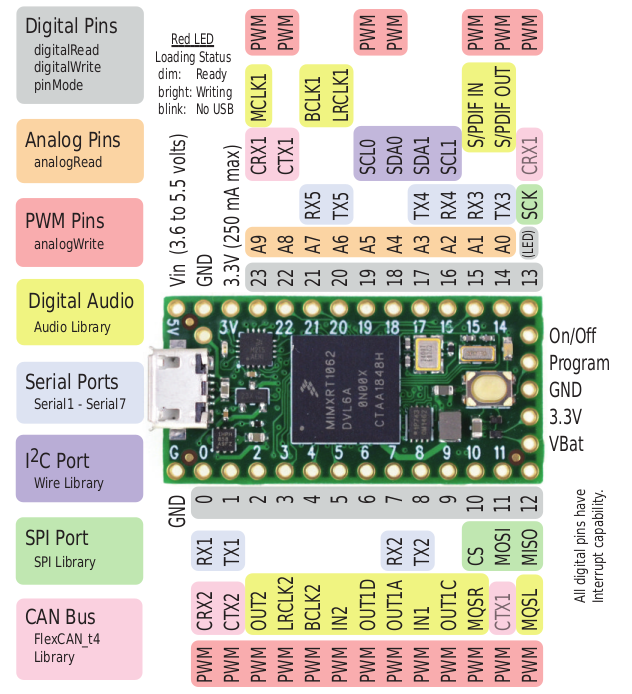
I am sure my mistake is simple but I have not found discussion of a similar problem. Is there a method I need to call to initialize pins 16, 17, 20 and 21 for output or did I just miss something about their capabilities in documentation? I confess I could not figure out the capabilities of AD_B1_00..ADB1_09 as shown at https://www.pjrc.com/teensy/schematic.html and described in https://www.pjrc.com/teensy/IMXRT1060RM_rev2.pdf.
Related, am I correct in my belief that pins 14..23 (A0..A9) are all true analog outputs from a DAC or are some PWM?
Thanks again,
Tom
I cannot find my error writing to analog outputs 16, 17, 20 and 21. Analog outputs 14, 15, 18, 19, 22 and 23 are working with no issue. digitalWrite() to pins 16, 17, 20 and 21 was tested separately with no issue. Both 8-bit (0..255) and 12-bit (0..4095) resolution were tested. The other libraries I am using in my project are Adafruit_MCP3008, Adafruit_MCP23017 (uses wire library not teensy4_i2c) and MAX31855 but they are not included in my test configuration.
My test function sends an increasing then decreasing signal to all pins. I tested with and without calls to pinMode() during setup. The issue is reproduced with the code below. test_analog() is called with setup = true for setup then with setup = false to execute. pinMode() is called in setup if callPinMode == true.
I am sure my mistake is simple but I have not found discussion of a similar problem. Is there a method I need to call to initialize pins 16, 17, 20 and 21 for output or did I just miss something about their capabilities in documentation? I confess I could not figure out the capabilities of AD_B1_00..ADB1_09 as shown at https://www.pjrc.com/teensy/schematic.html and described in https://www.pjrc.com/teensy/IMXRT1060RM_rev2.pdf.
Related, am I correct in my belief that pins 14..23 (A0..A9) are all true analog outputs from a DAC or are some PWM?
Thanks again,
Tom
Code:
#define TEST_SUCCESS 0

int test_analog(
    bool setup,
    bool callPinmode);

void setup() {
  Serial.begin(9600);
  test_analog(true, true);
  Serial.println("exit setup");
} // end void setup()

void loop() {
  test_analog(false, false);
} // end void loop()

int
test_analog(
    bool setup,
    bool callPinMode) {
  // setup
  if (setup == true) {
    // optional call to pinMode to test with and without
    // no action should be required prior to calling digital write
    if (callPinMode == true) {
      Serial.println("initialize analog outputs");
      for (int i=14; i<24; i++) {
        pinMode(i, OUTPUT);
      } // end for (i) pinMode()
    } else {
      Serial.println("analog outputs not initialized");
    } // end if (callPinMode == true)
    return TEST_SUCCESS;
  } // end if (setup == true)
  // execute
  Serial.println("analog inputs on");
  for (int i=0; i<256; i++) {
    for (int j=14; j<24; j++) {
      analogWrite(j, i);
    } // end for (j) analogWrite()
    delay(4);
  } // end for i (increasing)
  Serial.println("analog inputs off");
  for (int i=255; i>=0; i--) {
    for (int j=14; j<24; j++) {
      analogWrite(j, i);
    } // end for (j) analogWrite()
    delay(4);
  } // end for i (decreasing)
  return TEST_SUCCESS;
} // end test_analog()