garcho
Member
I have a MIDI master clock ready to be built but for the final few pieces of the puzzle.
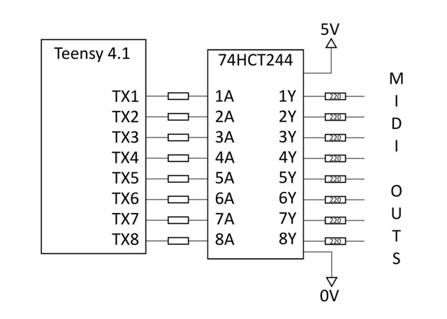
If I have 8 UART outputs going to 8 MIDI jacks, should I buffer each with a pair of inverters? Or will a 47Ω resistor in series with each TX pin be sufficient protection for the Teensy? This is a one-off for my own use, so "good enough" is actually good enough. If the answer is "yes, you should buffer them", then I will follow up with a few more questions in a separate reply.
Along with the UARTs, there is the 3V3 47Ω pull-up resistor for each MIDI out. If I have 8 MIDI outputs, that's 7mA each, for a total of 56mA, right? That leaves roughly 200mA left for the convertor to comfortably provide, yes? Is there anyway to guesstimate how much current my sketch will use? Am I safe assuming a MIDI clock sketch with a few LED/button functions is less than 200mA? Is there a better way to proved the power for the 5mA current loop than from the Teensy itself? I plan on using a 5V wall wart.
There will be 8 LED-lit buttons triggered by Teensy GPIO pins but I have each going through a 4k7 resistor to the base of a 2N3904, so hopefully that's 0.7mA per pin and not something to be concerned with?
There is also a 3V 16x2 RGB-on-black LCD display, with an I2C "backpack" (AVR ATMega328p). I'm not sure how to go about measuring total current draw but I could blindly guess and hope it's something like 30-50mA total, including backlight. I'm basically only using the blue LEDs, so it won't be like powering a flashlight or something. It's this particular model: https://www.sparkfun.com/products/14073. Like I said, I plan on powering it (and the Teensy) from an external 5V wall wart so I don't think it matters anyway. As far as the Teensy is concerned, it's only 2 more GPIO pins, right?
Any thoughts, suggestions, answers, haikus?
Thanks for your time!