Hi there,
First, I would like to thank you for this awesome resource here.
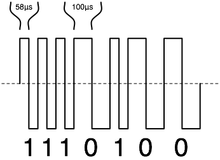
I would like to program an algorithm that creates the DCC signal which is used by model railroads.
I am wondering which function to use to create this signal. I will be using the Teensy 3.2 together with an H-bridge LMD18200T. This means I need to somehow create a square wave on one pin. The signal out of the Teensy will be composed of either 1 or 0. The 1 being a 58 microseconds long square wave and 58 microseconds long pause; the 0 should be a 100 microseconds long square wave with a 100 microseconds long pause (in fact it doesnt really matter whether the pause is before or after the wave). Also there is some tolerance: the 1 signal can be between 55 and 61 us long and 0 between 95 and 9900(!) us.
The LMD18200T will then use this signal from the Teensy to invert the input voltage from an external power supply accordingly and put it on the rails.
At this point I am not concerned with the algorithm itself, but the specific function to use for the 1 or 0 wave. As long as there is no new command (like a new speed setting) it should repeat all the old commands (in case an engine lost power for a brief moment so it does continue after it receives the repeated command).
Later I also want to put commands into arduino ide's serial monitor and have the Teensy put those commands onto the rails.
Reading posts about it I got the idea that PWM would be a good way of creating accurate signals.
TLDR: Which function in Teensy 3.2 is both easy to use and accurate enough to create a digital signal composed of 58 us and 100 us half square waves?
Edit: I do not know how to use the PWM (analogWrite?) function properly. All i could come up with myself was to use digitalWrite for the signal and elapsedMicros for timing. But I am not sure how this would turn out in a program that is also doing a lot of other stuff at the same time like waiting for input on serial, controlling led's and possibly a CAN bus later down the road.
First, I would like to thank you for this awesome resource here.
I would like to program an algorithm that creates the DCC signal which is used by model railroads.

I am wondering which function to use to create this signal. I will be using the Teensy 3.2 together with an H-bridge LMD18200T. This means I need to somehow create a square wave on one pin. The signal out of the Teensy will be composed of either 1 or 0. The 1 being a 58 microseconds long square wave and 58 microseconds long pause; the 0 should be a 100 microseconds long square wave with a 100 microseconds long pause (in fact it doesnt really matter whether the pause is before or after the wave). Also there is some tolerance: the 1 signal can be between 55 and 61 us long and 0 between 95 and 9900(!) us.
The LMD18200T will then use this signal from the Teensy to invert the input voltage from an external power supply accordingly and put it on the rails.
At this point I am not concerned with the algorithm itself, but the specific function to use for the 1 or 0 wave. As long as there is no new command (like a new speed setting) it should repeat all the old commands (in case an engine lost power for a brief moment so it does continue after it receives the repeated command).
Later I also want to put commands into arduino ide's serial monitor and have the Teensy put those commands onto the rails.
Reading posts about it I got the idea that PWM would be a good way of creating accurate signals.
TLDR: Which function in Teensy 3.2 is both easy to use and accurate enough to create a digital signal composed of 58 us and 100 us half square waves?
Edit: I do not know how to use the PWM (analogWrite?) function properly. All i could come up with myself was to use digitalWrite for the signal and elapsedMicros for timing. But I am not sure how this would turn out in a program that is also doing a lot of other stuff at the same time like waiting for input on serial, controlling led's and possibly a CAN bus later down the road.
Last edited:

