Teensy 3.2 with the adafruit airlift - no joy.

Status
Not open for further replies.

owhite

Active member
Folks,

I have tried using the Adafruit airlift module with a teensy 3.2 using the wiring and code suggested here:
https://github.com/j3nsykes/OSC_propShield

I've checked all pin connections, they're solid. I'm using a separate power supply - the airlift is not dependent on the USB mAmperage. I'll post the code below, but notice that I try:

Code:
  // check for the WiFi module:
  while (WiFi.status() == WL_NO_MODULE) {
    Serial.println("Communication with WiFi module failed!");
    // don't continue
    delay(1000);
  }

and I get:
MAC: 00:00:00:00:00:00
Communication with WiFi module failed!

I promise I've been a good citizen and read all the posts on the forum about using the airlift and it still aint working.

Any suggestions!?

thanks,

o

Code:
#include <SPI.h>
#include <WiFiNINA.h>

#define SPIWIFI     SPI
#define SPIWIFI_SS    10  // Chip select pin
#define SPIWIFI_ACK   7   // a.k.a BUSY or READY pin
#define ESP32_RESETN  5   // Reset pin
#define ESP32_GPIO0   -1  // Not connected

void setup() {
  //Initialize serial and wait for port to open:
  Serial.begin(9600);
  while (!Serial) {
    ; // wait for serial port to connect. Needed for native USB port only
  }

  Serial.println("WiFi Scanning test");

  // Set up the pins!
  WiFi.setPins(SPIWIFI_SS, SPIWIFI_ACK, ESP32_RESETN, ESP32_GPIO0, &SPIWIFI);

  // print your MAC address:
  byte mac[6];
  WiFi.macAddress(mac);
  Serial.print("MAC: ");
  printMacAddress(mac);

  // check for the WiFi module:
  while (WiFi.status() == WL_NO_MODULE) {
    Serial.println("Communication with WiFi module failed!");
    // don't continue
    delay(1000);
  }
  String fv = WiFi.firmwareVersion();
  Serial.println(fv);
  if (fv < "1.0.0") {
    Serial.println("Please upgrade the firmware");
    while (1) delay(10);
  }
  Serial.println("Firmware OK");

}

void loop() {
  // scan for existing networks:
  Serial.println("Scanning available networks...");
  listNetworks();
  delay(10000);
}

void listNetworks() {
  // scan for nearby networks:
  Serial.println("** Scan Networks **");
  int numSsid = WiFi.scanNetworks();
  if (numSsid == -1) {
    Serial.println("Couldn't get a wifi connection");
    while (true);
  }

  // print the list of networks seen:
  Serial.print("number of available networks:");
  Serial.println(numSsid);

  // print the network number and name for each network found:
  for (int thisNet = 0; thisNet < numSsid; thisNet++) {
    Serial.print(thisNet);
    Serial.print(") ");
    Serial.print(WiFi.SSID(thisNet));
    Serial.print("\tSignal: ");
    Serial.print(WiFi.RSSI(thisNet));
    Serial.print(" dBm");
    Serial.print("\tEncryption: ");
    printEncryptionType(WiFi.encryptionType(thisNet));
  }
}

void printEncryptionType(int thisType) {
  // read the encryption type and print out the name:
  switch (thisType) {
    case ENC_TYPE_WEP:
      Serial.println("WEP");
      break;
    case ENC_TYPE_TKIP:
      Serial.println("WPA");
      break;
    case ENC_TYPE_CCMP:
      Serial.println("WPA2");
      break;
    case ENC_TYPE_NONE:
      Serial.println("None");
      break;
    case ENC_TYPE_AUTO:
      Serial.println("Auto");
      break;
    case ENC_TYPE_UNKNOWN:
    default:
      Serial.println("Unknown");
      break;
  }
}


void printMacAddress(byte mac[]) {
  for (int i = 5; i >= 0; i--) {
    if (mac[i] < 16) {
      Serial.print("0");
    }
    Serial.print(mac[i], HEX);
    if (i > 0) {
      Serial.print(":");
    }
  }
  Serial.println();
}
 
Asking the obvious probably but did you exactly wire it up as indicated on the OSC_propShield page?
Also the code seems OK as far as I can see. I noticed though that you want to print out the MAC address first and then check for the module to be present. Guessing it shouldn't be an issue but I would reverse this order just be sure [and logical].
Did the compiler spit out any warnings?
And perhaps if you have an oscilloscope you can check the module voltages and SPI bus for abnormalities.

Paul
 
PaulS,

thank you for your response. I have followed the wiring of the OSC_propShield page exactly. The choice to check the MAC address first was based on the statement here:

https://learn.adafruit.com/adafruit-airlift-breakout/arduino

"If you don't even get the MAC address printed out, check your wiring."

The compiler does not issue any warnings.

Voltage levels on some of the pins:
GND - 0.0v
Vin - 5.0v
Reset - 5.0v
Busy - 3.3v
CS - 5.0v

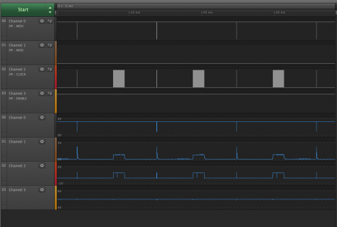
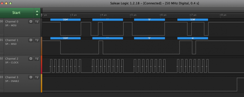
I did not expect to see CS go high at 5v. When I disconnect that from pin 10 on the teensy it remains high on the device and the teensy pin 10 is 0.0v. That doesnt seem right to me. I have an oscilloscope and checked all my readings, and i have attached a picture from a logic analyzer. The logic analyzer is showing in the analog readings that MISO and CLK are not getting above 1 volt. This also seems suspicious.

To make this picture I took the delay out of above program

Code:
  // check for the WiFi module:
  while (WiFi.status() == WL_NO_MODULE) {
    // Serial.println("Communication with WiFi module failed!");
    // delay(1000);
  }

Logic analyzer results are below.

To summarize so far it seems like CS is not going to actively low on the device and the CLK is not supplying any timing..

o

Screen Shot 2020-08-15 at 7.56.44 AM.png
 
KurtE,

Yah i was looking forward to this thing sending telemetry data to for a balanceBot - I think it will be great. Yes, on this page:
https://github.com/j3nsykes/OSC_propShield
He also notes to use that library to be able to change pin settings. I've been using that library.

I'll report back if I get it going.
 
MarkT,

my cheapo voltmeter with continuity checker does not find a short between CS and +5v. I have two airlift modules. When I measure between GND and CS I get about 800 ohms on both. Other suggestions to check?

I think i have an arduino laying around and I might try connecting the module to that, but I'm not sure that would tell me much about how to get it working on the teensy.

all ideas welcome.

o
 
MarkT,

thanks for pointing me to the schematic. So maybe the teensy is not able to take it low for some reason. I'll put a square wave out on that pin and take a look at it on the scope.

owen
 
Hi Owen,

When I look at the analog readings of your graph above, it seems there is a short between the MISO [ch 1] and the CLK [ch 2] line?

Paul
 
Note in cases like this, it can really help to see pictures of the actual setup.

We might be able to see if it looks like bad (or no) solder joints of pins, likewise maybe see shorts. Or maybe see missing a common ground pin, or maybe you thought you were on pin 5 but was on pin 4...

Also since you have it on Logic Analyzer, what speed is it measuring the SPI clock at? I think I read it can handle 8mhz?
 
First of all I apologize to people because one thing I'm learning is this module needs to get a full reboot for it to behave. If i keep the usb connected, and program using platformio and then take measurements it seems like it locks up - and I think that accounts for the strange behavior with CS. Basically all previous timing diagrams should be ignored and you'll see a new timing diagram in a second.

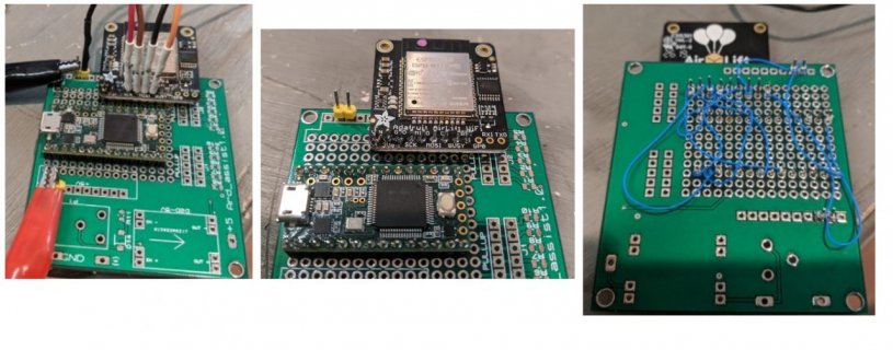
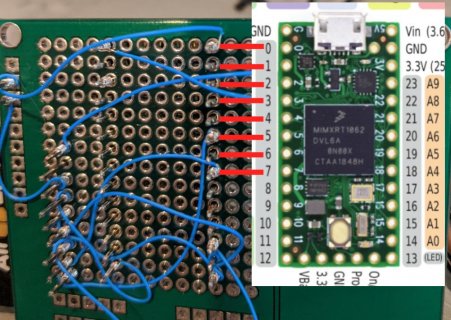
As for my wiring. I have checked all connections for shorts between pins and there are none. I designed a custom PCB to use to make wirewrap prototypes with teensy 3.2s. Pictures are attached. After this post i'll send a couple screen shots of the logic analyzer.

thanks for everyone's help!
Screen Shot 2020-08-15 at 9.52.11 AM.jpg
 
Last edited:
Hi Owen, a quick one before you post logic analyzer images: could you set the analog scale of all 4 signals to 0-5V?
Thanks,
Paul
 
No problem as the analog sample frequency [2.5MHz] is way too low to capture fast phenomena. Can you set the Saleae to a higher digital sample rate? Perhaps by ommiting analog capture?
Also 5MHz for a 8MHz SPI clock is too slow - that's probably why you see missing clock pulses.
Anyway, I'm still a bit puzzled by the fact that I see MOSI and MISO both active at the same SPI clock pulses. I would expect to see MOSI data first and then later MISO data returning. But perhaps this is allowed and possible on SPI.

Paul
 
Quick FYI - I ordered one of the Adafruit units from Amazon, should be here maybe next Thursday...

On LA software, you might try out their probably soon to be released Version 2 stuff... More info up at: https://discuss.saleae.com/

Looking at your photos. I could be wrong, but your code is setup for:
Code:
#define SPIWIFI_ACK   7   // a.k.a BUSY or READY pin
#define ESP32_RESETN  5   // Reset pin

But if I am looking correctly at the last image with the wire wrap, it almost looks like you are on 6 and 4?

Could be I am just looking at it wrong, but you might want to simply ring it out to make sure.

EDIT: And speed wise not sure which Logic you have? I assume 8 or pro 8... But I know you should be able to go a lot faster. Note: I normally don't setup to receive Analog unless I am looking for something very specific...
 
Youre right, when analog samples are not collected you can increase sampling speed.

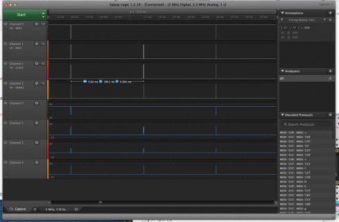
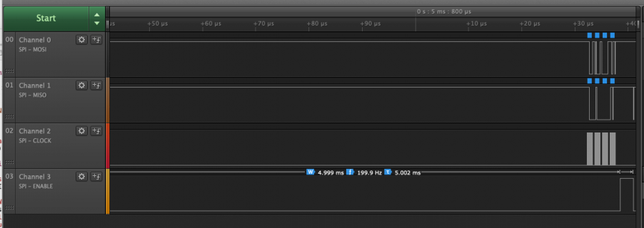
Screen shot:
Screen Shot 2020-08-15 at 10.39.28 AM.png
Notice that this is after a very long (5ms) of CS going low.
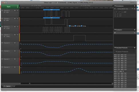
Screen Shot 2020-08-15 at 10.43.05 AM.png
 
KurtE,

thank you VERY much for looking at my wire wrap so carefully.

Here's an overlap between my pins and the teensy - I'm definitely connected to 5 and 7.

Screen Shot 2020-08-15 at 10.53.06 AM.jpg

Regarding clock speed - yes, I've managed to get it faster as shown in last post.

And great to hear youre getting a similar module. Misery loves the company. :)
 
WAIT A SECOND!

Oh my god KurtE is right. Look at my picture. It's off by one and so am I. Just shoot me now.
 
WAIT A SECOND!

Oh my god KurtE is right. Look at my picture. It's off by one and so am I. Just shoot me now.

That is what I wondered if you did not count the GND pin when you were wiring it. Hope it works (fingers crossed)
 
And believe me, I have done similar things (although no wire wrapping) before! (Many Times)

So I keep on hand a sketch that @defragster an myself hacked up, called HiLowTest
Code:
void setup() {
  Serial.begin(115200);
  while (!Serial && millis() < 4000 );
  Serial.println("Compile Time:: " __FILE__ " " __DATE__ " " __TIME__);
  Serial.printf("Num Digital Pins: %d\n", NUM_DIGITAL_PINS);

  testForShorts();
  
}

uint32_t cnt = 0;
void loop() {
  cnt++;
    allPinTest( cnt );
}

uint32_t pinLast[NUM_DIGITAL_PINS];
void allPinTest( uint32_t cnt ) {
  uint32_t ii, SET;
  Serial.print("PULLDOWN Start Vals:\n  ");
  SET = 0;
  Serial.print("PULLDOWN :: TEST to 3.3V\n  ");
  for ( ii = 0; ii < NUM_DIGITAL_PINS; ii++) {
    pinMode( ii, INPUT_PULLDOWN );
    delayMicroseconds( 5 );
    pinLast[ii] = digitalReadFast( ii );
    if (pinLast[ii]) {
      Serial.print("\nd#=");
      Serial.print( ii );
      Serial.print( " val=" );
    }
    Serial.print( pinLast[ii] );
    Serial.print(',');
  }
  Serial.println();
  Serial.println();
  while ( 1 ) {
    uint32_t jj, dd = 0, cc = 0, ee=4;
    cc = 0;
    for ( ii = 0; ii < NUM_DIGITAL_PINS; ii++) {
      jj = digitalReadFast( ii );
      if ( jj != pinLast[ii] ) {
        dd = 1;
        cc++;
        pinLast[ii] = jj;
        Serial.print("d#=");
        Serial.print( ii );
        if ( pinLast[ii] ) Serial.print( "\t" );
        Serial.print( " val=" );
        Serial.print( pinLast[ii] );
        Serial.print(',');
      }
      if ( cc > 1 && ee ) {
        Serial.println(">>> MULTI CHANGE !!");
        ee--;
      }
      if ( Serial.available() ) {
        while ( Serial.available() ) Serial.read();
        if ( 0 == SET ) {
          SET = 1;
          Serial.print("PULLUP :: TEST TO GND\n  ");
        }
        else {
          SET = 0;
          Serial.print("PULLDOWN :: TEST to 3.3V\n  ");
        }
        for ( ii = 0; ii < NUM_DIGITAL_PINS; ii++) {
          if ( 0 == SET )
            pinMode( ii, INPUT_PULLDOWN );
          else
            pinMode( ii, INPUT_PULLUP );
          delayMicroseconds( 20 );
          pinLast[ii] = digitalReadFast( ii );
          if (SET != pinLast[ii]) {
            Serial.print("d#=");
            Serial.print( ii );
            Serial.print( " val=" );
            Serial.println( pinLast[ii] );
          }
        }
      }
    }
    if ( dd ) {
      dd = 0;
      Serial.println();
      delay( 50 );
    }
  }
}

void testForShorts() {
  uint32_t ii;
  Serial.print("Quick Test for Shorts to adjacent pin");
  Serial.println("First pull pins down and see if the next one follows");
  for ( ii = 0; ii < NUM_DIGITAL_PINS-1; ii++) {
    pinMode( ii+1, INPUT_PULLDOWN );
    pinMode( ii, OUTPUT);
    digitalWrite(ii, HIGH);
    delayMicroseconds( 5 );
    if (digitalRead(ii+1)) {
      Serial.printf("%d:%d ", ii, ii+1);
    }
  }
  Serial.println("\n Now try Pull up and see if setting low follow");
  for ( ii = 0; ii < NUM_DIGITAL_PINS-1; ii++) {
    pinMode( ii+1, INPUT_PULLUP );
    pinMode( ii, OUTPUT);
    digitalWrite(ii, LOW);
    delayMicroseconds( 5 );
    if (!digitalRead(ii+1)) {
      Serial.printf("%d:%d ", ii, ii+1);
    }
  }
  Serial.println();  
}
Which you can go between two modes of either setting all pins either PU or PD and then you use a jumper wire to either 3.3v or GND, and then touch a pin and see it tells you which pin or pins changed state....
 
KurtE and PaulS,

I owe both of you an apology. This was entirely because of bad wiring.

I have a MAC address and the module is now scanning my local wifi networks.

This is an incredible example of patience on the part of both of you and I very much appreciate your time.

This is great news because i already designed and ordered a custom PCB for this module to tie into a teensy 4.0. (and yes I just checked it's wired correctly).

KurtE - I simply can not believe you caught that. And wow - that's a great program - thank you several times over.

sincerely,

owen
 
Status
Not open for further replies.
Back
Top