I bought a Tall-Dog Breakout Board for the Teensy 4.0, to replace the smoked Teensy 3.5 I have.
This time I bought it assembled. All I had to do was install the header pins for the I/O I need.
This will be installed in a box with a panel mounted USB port. As I am using an external (to the Teensy) power supply I do not need the USB supplied power.
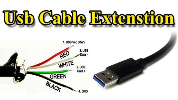
I hooked up the D+ and D- (and ground) pins on the Breakout Board to the panel mounted USB jack and nothing happens. But if I use the micro USB port on the Teensy 4.0 itself, everything works as it should. I can load a modified (faster blink rate) blink sketch and it works.
Anyone here know how I can get the D+ and D-pins to work?
How should the switches on the Breakout Board be set? In the far distant future this will be exchanging data and commands with a laptop, but for now it will be used just for uploading the sketch.
There is a button on the Breakout Board that doesn't seem to do anything. What is it for?
I do not see any user information on the Tall-Dog website.


