Hey 
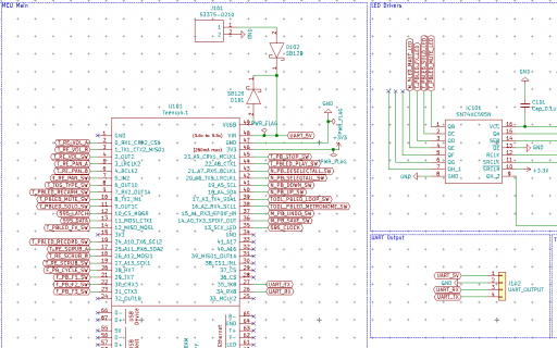
I'm putting the final touches on a MIDI controller and I have added provisions for powering another Teensy and having it communicate via UART.
Currently I've just got 4 pins
- 5v out from VIN to provide Power to another t4.0 via its vin pin
- GND
- RX
- TX
Question 1 - Should I have protection or isolation from the VIN pin?
Question 2 - should RX and TX be optoisolated to prevent against reversed polarity or over voltage coming back to damage the UART RX and TX? (6N138 maybe)
Thanks


