Fast DAC shield for Teensy

Status
Not open for further replies.

Tem

New member
Hello!
Is it poosible to use the TeensyAudioBoards (C, D) down to DC = 0 Hz, like a simple DAC (or do they have a minimum frequency)?
If it's possible, is there a software support on that DAC feature (DAC commands,...), independent on audio applications?

If this is not possible, is there any ready small DAC board with two (better more) channels, 16 Bits, >40 kHz?

Of course I know, there are many chips from Analog Devices, Maxim, etc. But I want to avoid making an own PCB and complete new software, but use it fitting to Teensies (which I'm a fan of!).
Has anybody good experiences and example codes (maybe also with demo boards of the chip manufacturers)?
Thanks in advance!

The schematics for rev C and rev D show that the line ins and outs are AC-coupled, using 2.2µF capacitors,
which finesses the question.

Many I2S DACs are DC capable, the datasheets don't usually make it obvious though, you have to figure
out if there's a subsonic filter and if so whether it can be turned off.
 
The schematics for rev C and rev D show that the line ins and outs are AC-coupled, using 2.2µF capacitors,
which finesses the question.

Sure, of course I meant by bypassing the capacitors, and taking care of the DC offsets, in and out.
In the schematics there is no resistor, neither at IN nor at OUT lines, which defines the lower cut-off frequency, together with the 2.2uF. (With 29 kOhms Line Input impedance of the SGTL5000 data sheet it would be 2.5 Hz, fine for full audio!
But for example with 1k load at the outputs it would be just 80 Hz! No real bass!)
However the MIC input line has 100 nF, and an impedance of 2.9 kOhms, which leads to a lower cut-off frequency of 550 Hz, which is VERY high, definitely no bass at all, why?

OK, I want to skip the capacitors. However, there are filters inside the chip, EQs, audio processing, so it could be possible, that the bandwidth is limited to audio range (I did not find in the data sheet). And there are more audio-related features (for example gain setting just at zero-crossing of the audio signal to avoid popping, etc.), which could be very confusing and annoying for using with non-audio (DC) signals...

Maybe the small "PJRC - PT8211 Audio Kit" is a well fitting solution for using as a DAC, better than the complicate SGTL5000? Has anyone tried that?
 
Sure, of course I meant by bypassing the capacitors, and taking care of the DC offsets, in and out.
In the schematics there is no resistor, neither at IN nor at OUT lines, which defines the lower cut-off frequency, together with the 2.2uF. (With 29 kOhms Line Input impedance of the SGTL5000 data sheet it would be 2.5 Hz, fine for full audio!
But for example with 1k load at the outputs it would be just 80 Hz! No real bass!)
Line load impedances are assumed to be 10k to 50k, the SGTL5000's inputs are 29k, so not a problem for cutoff, just
there to remove DC bias - they are probably not NP0 caps, so you definitely don't want appreciable signal voltage across them.

The SGTL5000 datasheet specifies a minimum load of 10k for the line outs.
However the MIC input line has 100 nF, and an impedance of 2.9 kOhms, which leads to a lower cut-off frequency of 550 Hz, which is VERY high, definitely no bass at all, why?
That's a shield design bug surely. Hadn't noticed its effects, but it will be dependent on the mic gain setting perhaps?
That's probably done with switched resistors in an inverting opamp topology.
OK, I want to skip the capacitors. However, there are filters inside the chip, EQs, audio processing, so it could be possible, that the bandwidth is limited to audio range (I did not find in the data sheet). And there are more audio-related features (for example gain setting just at zero-crossing of the audio signal to avoid popping, etc.), which could be very confusing and annoying for using with non-audio (DC) signals...

Maybe the small "PJRC - PT8211 Audio Kit" is a well fitting solution for using as a DAC, better than the complicate SGTL5000? Has anyone tried that?

You know audio DACS often aren't very accurate for use at DC - the gain and offset depends on the on-chip sigma-delta current
sources which aren't normally laser-trimmed to my knowledge - 0.1dB variation between channels and devices isn't a big issue
for audio. They usually cannot span the full range from GND to Vcc either due to the architecture, nor can they normally be referenced
to an external voltage reference.
 
Maybe the small "PJRC - PT8211 Audio Kit" is a well fitting solution for using as a DAC, better than the complicate SGTL5000? Has anyone tried that?
Yes, just tried it.
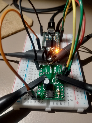
Here is the setup:

IMG_20200826_204512.png

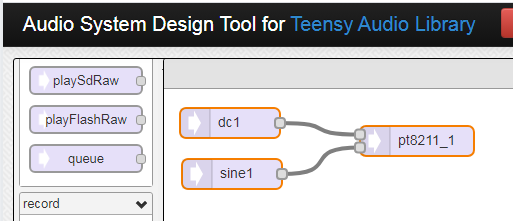
Here is what I did in the Audio System Design Tool:

Capture.PNG

Here is the code:

Code:
// PT8211 bd    Teensy
// VCC          3V3
// GND          GND
// WS           23
// DIN          22
// BCK          9
// --           11 (MCLK)

#include <Audio.h>

AudioSynthWaveformDc     dc1;            //xy=248,1206
AudioSynthWaveformSine   sine1;          //xy=250,1270
AudioOutputPT8211        pt8211_1;       //xy=457,1232
AudioConnection          patchCord1(dc1, 0, pt8211_1, 0);
AudioConnection          patchCord2(sine1, 0, pt8211_1, 1);

void setup()
{
  AudioMemory(12);
  pinMode(LED_BUILTIN, OUTPUT);
  digitalWrite(LED_BUILTIN, HIGH);

  sine1.frequency(1);
  sine1.amplitude(1.0);  // 0dB
  dc1.amplitude(0.0);
}

void loop()
{
  dc1.amplitude(1.0);
  delay(1000);
  dc1.amplitude(-1.0);
  delay(1000);
}

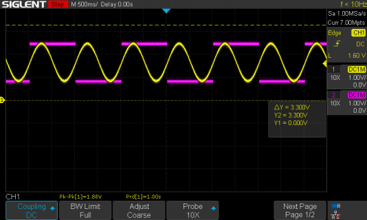
And here is the output on the oscilloscope:

SDS00006.png

So it seems to work but take note of the remarks MarkT made in his last paragraph.

Paul
 
Thanks to MarkT and PaulS!
I have ordered both PCBs from PJRC (here in Germany the small PT8211 Kit is momentarily not available) and will play with them soon...
First I have to dive into the Teensy Audio Tools, try out your example, before I can ask new questions (about fast DAC output commands, e.g.).
Offset and gain drifts are not that problem in my application, because it's all within in a servo loop, externally referenced.
Rail-to-rail also isn't an issue, I have to offset the outputs anyway, approx. symmetrical to zero.
I only need resolution and some speed.
Regards again, Tem
 
Status
Not open for further replies.
Back
Top