How *loud* should my audio out be?

Status
Not open for further replies.

jidagraphy

Active member
Short version :
Im gonna drive an audio out from the onboard DAC. I'm going to use an opamp to drive my signal to a 'commercial standard' of synth line levels. How much max voltage/current/loudness should my final signal be?
or what circuitry should I be using from my DAC pin to my 3.5mm audio jack?

Kinda longer version:
Situation as above, I'm gonna be driving my signal through an MCP6002 opamp from my teensy's onboard DAC, with internal reference of 0v-1.2v. And of course, i'll have a capacitor in series before the opamp that will remove the 0.6v dc offset. (Maybe a safety 1k resistor at the end? not sure yet)

Now I'm a little baffled as to how I should set my final signal. I want my synth to be at a similar level as my other commercial synths (Korg Volcas, TE OP-1 and PO series, etc) but I'm worried I might mess up my mixer or audio interface with wrong voltage/current/impedance setting. I'm worried that I might maybe over amplify/ send too much current and whatnot.

Instead of trying to ask what I dont understand, I'll list some use cases for my synth.

- I would want to be able to listen on any commercial earphones. Apple Earpods, for example.
- I could connect my synth to my mixer (Korg Volca Mix), alongside my other synths (Korg Volca Keys, Modular, FM, Teenage Engineering OP-1, PO series etc). It says on their specification that the mixer expects a (maximum of, i think?) 0dBu signal from its inputs?
- Or maybe I could drive my synth through my audio interface Focusrite Clarett 8Pre's input?
- I dont know if i would ever do this, but for my curiosity's sake, what about if I drive the already-amplified signal to a guitar amp? or any other amplifiers? I would guess this wouldn't really make any difference as a lot of synth already amplifies out going signal anyway, right?


Yeah... coding is rarely my problem but electronics always gets me :(
So my question - what should I do, circuit-wise, between my teensy's DAC pin and the outputting 3.5mm audio jack?

Thank you guys always.

Jin
 
oh something to add.

Werid thing I noticed is that when I plug my earphones directly to the DAC pin, i could barely hear the signal. But when I connect it to my mixer, its nearly similar to my other commercial synths. I find it werid because I would have expected the synth to still sound very quiet through the mixer.

I wonder why hmm
 
oh something to add.

Werid thing I noticed is that when I plug my earphones directly to the DAC pin, i could barely hear the signal.

Earphones are typically 16 ohm, seen by the DAC pin as pretty much a dead-short, hopelessly overloading it - this
is not a safe thing to do to a logic pin, especially as earphones are inductive loads and could over-voltage the pin
too (as well as over-current the driver FETs).
 
Earphones are typically 16 ohm, seen by the DAC pin as pretty much a dead-short, hopelessly overloading it - this
is not a safe thing to do to a logic pin, especially as earphones are inductive loads and could over-voltage the pin
too (as well as over-current the driver FETs).

Hmm! Okay. Thanks!
How about those consumer synthesizers that only has, what it looks to be a headphone out, to be used as the only audio out? like these? It seems to work with earphones and as line-in. I can't seem to find any info about their impedance and whatnot, so what would your guess be?
 
Hmm! Okay. Thanks!
How about those consumer synthesizers that only has, what it looks to be a headphone out, to be used as the only audio out? like these? It seems to work with earphones and as line-in. I can't seem to find any info about their impedance and whatnot, so what would your guess be?

Obviously a headphone output is able to drive headphones and earphones, the name gives it away - so they will clearly
be able to drive 16 ohms, and probably 8 ohms come to that - they are amplified outputs, doubling as line outputs too.

A DAC produces a signal, not power, and isn't amplified nor buffered usually. Most DACs could drive a line output (50k is the nominal
load impedance for line signals), but its always wise to buffer a DAC to both protect it from the outside world and to
present a low source impedance to the load. This is how analog audio signaling is done, low impedance output into high impedance
input. Low impedance outputs are typically 0 to 100 ohm, but normally start to distort if presented with less than 1k load
resistance.

Using a single headphone out to save lineout connectors and cost is a compromise.

Right!
I wanted to confirm that the amplified output does infact double as line output too. Thanks for clarifying. So I guess thats why i should have to amplify it first - to lower the impedance, I guess?

Okay I think I understand it. Thank you always, MarkT!

If you aren't too busy - Could you also help me imagine how I should configure my opamp between the DAC and the outside world?

As I understand it, the DAC would normally output 3.3v at 1mA, which means 3.3kOhm outgoing impedance. I can't imagine how I should lower that down to less than few hundreds, with an opamp?!

Thanks
 
Okay i found this :

https://www.eecs.tufts.edu/~dsculley...s/opamps5.html

I thought I would have to amplify my signal with some complicated setup, but i didn't know about opamp buffer configuration. Now I'm imagining this :

DAC -> 10uF capacitor in series -> OPAMP buffer (or amp?) -> optional 10k potentiometer volume control -> 3.5mm audio jack

Do you reckon this would be an alright signal flow?
 
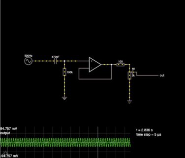
Well you've neglected DC bias of the opamp input that way, and 10µF is huge considering. 470nF to the opamp input, with 100k bias
resistor to ground perhaps. You need ~100 ohms on the output of opamps for stability if driving a cable. 2k output pot for
volume control would be a better choice to keep the impedances low.
 
Hey, few things.
what does this mean? You meant that I removed DC bias with the capacitor so I dont have to worry about it later right?
Well you've neglected DC bias of the opamp input that way

Why do I need a 100k resistor to the ground? and where?
470nF to the opamp input, with 100k bias
resistor to ground perhaps.


Woud this be the correct circuitry you recommended?
Screenshot 2020-08-28 at 7.27.12 PM.jpg

Webversion : link

Thank you!
 
Well you'll need supply rails too, +/-5V perhaps,

If you want 5V single supply you'll need a large output capacitor, 47uF or so, and a rail-to-rail opamp that's reasonable
for audio (not an LM358 or a micropower opamp, my go-to is the AD8656 which has excellent drive capability).
 
Well you'll need supply rails too, +/-5V perhaps,

If you want 5V single supply you'll need a large output capacitor, 47uF or so, and a rail-to-rail opamp that's reasonable
for audio (not an LM358 or a micropower opamp, my go-to is the AD8656 which has excellent drive capability).

YupYup.
I was gonna use the MCP6002, but im reconsidering if I want rail to rail or single supply. Why not the LM358? bad quality? I just looked for the AD8656 but it seems to only be as SMD haha Im still looking for DIP ICs hehe.
 
Or if i didn't care about gain amplification, I could just do this?

LINK

i.e. opamp as a buffer (or gain, if i want to i guess) first, and THEN a capacitor. this way I could just use the 3.3v supply from the teensy, right? though I haven't a clue how the size of the capacitor affects the signal.

edit : I dont know how to show voltage supply for the opamp on the falstad circuit simulator haha, but right now its 3.3v and 0
 
Sure, you could do something like that (a unity gain config for the opamp) and it would probably work reasonably well if the opamp has both rail-to-rail input *and* output. When shopping for opamps, some will loudly advertise rail-to-rail on web pages and the intro page of their datasheet, then quietly mention in the specs that it's only rail-to-rail output but not input. Buyer beware.

Always keep in mind that datasheets are written by marketing departments. They are advertisements. The datasheet's main purpose is to convince you to buy the product. They will always highlight the good selling points and sweep the less desirable trade-offs under the rug, sometimes even omitting certain specs completely and hoping you don't notice their absence.

Knowing a bit about how opamps are designed internally and the various trade-offs can really help to spot those less beautiful aspects that the datasheets don't highlight. Rail-to-rail input is typically made by creating 2 parallel input stages, where one has PNP or P-channel transistors, so it can work with voltages all the way down to (and maybe even slightly below) the negative rail, and the other with NPN or N-channel transistors, so it can work up to the positive rail. The downside to the approach is you tend to get 3 distinctly different amplifiers, depending on whether only the NPN, only the PNP, or both input circuits are passing your signal on to the rest of the opamp's internal circuitry. Usually the result is some amount of signal distortion, which of course is attenuated by the ratio of the opamp's open loop gain to whatever closed loop gain you circuit imposes. Maybe an issue, maybe not...

Rail to rail output is simpler, usually done with mosfet output transistors. The main issue is the output stage much have some voltage gain, since the transistors need to be connected as common source. Using common drain give lower (stronger) output drive and doesn't add more phase shift, which allows the whole amplifier to have better high frequency response. Modern chips are pretty good, so these probably won't matter to most people for ordinary audio where the opamp drive only resistive loads.

One other non-opamp thing to consider is whether to attenuate the signal after the opamp. Normally this isn't done, because it gives different output impedance depending on the position of the pot. Usually you would want a consistent low output impedance, like that 100 ohm resistor (plus whatever the opamp's closed loop output impedance is... usually just a few ohms for unity gain).
 
Paul,

Thanks for the detailed advice! Its a little difficult for me to fully understand but i'll take it as : 'check carefully if both the input and output is rail to rail'. Fortunately, I found MCP6002 to have rail to rail input and output.

But just to clarify, *why* is it important that they're rail to rail? If it wasn't going to amplify nor use all of the range of the opamp (whether its -5v to +5v or 0 to 5v), shouldn't it be fine?

The MCP6002 has 1MHz bandwidth and takes 0.1mA of supply current - order of magnitude out of quality
audio league I'm afraid, its a micropower chip (the low quiescent power consumption is the giveaway).

You want say 20--40MHz gain-bandwidth-product, 4mA quiescent current or so, then it can handle all audio
frequencies with low distortion, the MCP6002 will start to flag out above 1kHz with rapidly rising distortion -
it'll amplify, but not accurately.

For a 5V single rail system you need rail-to-rail or it simply won't work with a 5V DAC, since DACs are often
rail-to-rail or close. Non-rail-to-rail devices lose 1.5--2.5V on either or both rails on the output. If you can
provide supply rails of at least +7 and -2V you'd be able to use most opamps to buffer that DAC at DC.
 
The DAC on Teensy 3.2, 3.5 & 3.6 can output a 0 to 1.2V range, or a 0 to 3.3V range.

The 1.2V range gives better quality, so the audio library defaults to using that range. The 3.3V range uses the 3.3V power supply as the DAC's reference voltage, so any noise present on the 3.3V power can couple to your output signal. The 1.2V range uses the stable internal reference voltage.

So while you could use the 3.3V range, for best quality you should plan on the 1.2V range and whatever amplifier gain you need to boost it up to the range you want for your synth.
 
The MCP6002 has 1MHz bandwidth and takes 0.1mA of supply current - order of magnitude out of quality
audio league I'm afraid, its a micropower chip (the low quiescent power consumption is the giveaway).

You want say 20--40MHz gain-bandwidth-product, 4mA quiescent current or so, then it can handle all audio
frequencies with low distortion, the MCP6002 will start to flag out above 1kHz with rapidly rising distortion -
it'll amplify, but not accurately.

For a 5V single rail system you need rail-to-rail or it simply won't work with a 5V DAC, since DACs are often
rail-to-rail or close. Non-rail-to-rail devices lose 1.5--2.5V on either or both rails on the output. If you can
provide supply rails of at least +7 and -2V you'd be able to use most opamps to buffer that DAC at DC.

Right.. theres so much I didn't even anticipate!
Thanks for the recommendation! I'll look into this.

Thanks always MarkT!
 
So while you could use the 3.3V range, for best quality you should plan on the 1.2V range and whatever amplifier gain you need to boost it up to the range you want for your synth.

Yup! That's what I'm planning to do.
This thread got side tracked a little, but the initial question was how I should plan the circuitry between my 0v~1.2v DAC pin and an audio out jack. Or more like, what an 'appropriate' level of voltage a typical consumer synthesizer should be.

I learned that before worrying about voltage, I should try to match the impedance for the application I need. I'm thinking I should lower it as low as a headphone out, which can play into both typical earphones and line in. And thats when we talked about opamp/buffer/unity gain opamp/which opamp etc.

Do you have any other suggestions regarding processing the final signal?
 
Status
Not open for further replies.
Back
Top