
Hi guys!
I have been working on this project.
It is an arduino based gaming locomotion system.
Practically the project is about 2 accelerometers and 2 pressing sensors mounted at each shoe, and also 1 accelerometer at the chest, to control the movements-locomotion in games of the avatar/to control the movements of the joystick of game controllers.
For now the arduino sensors are connected to an arduino uno digishield . The digishield is connected in parallel to the digipot of the controllers that I want to control via the use of this arduino system.
This is the arduino uno digipot shield that I use
https://iorodeo.com/products/digital-potentiometer-shield
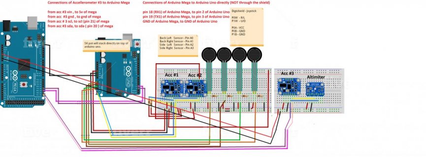
This is the original schematic I used for the mega-uno

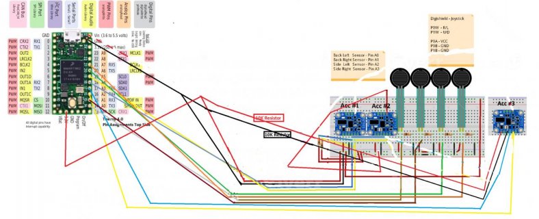
This is how I think the schematic would look like when connecting my arduino sensors to the teensy 4.0

One of the reasons why I am moving from the arduino mega-uno system to the teensy 4.0 , is because on the arduino mega-uno system , the chest accelerometers would not work properly in combination with the feet sensors (2 acceleroemtrs and pressing sensors).
I hope that the teenst 4.0 would allow me to use 3 bno055 accelerometers at the same time. The two accelerometrs at the feet would be connected on the 1st i2c channel, while the 3rd accelerometer (the chest accelerometer) would be connected to the a 2nd i2c channel.
The arduino codes I am using can be found here:
https://github.com/marcob2178/Shoes-controller
https://github.com/marcob2178/Chest-Controller
I am sure I will have more questions when starting migrating the code to the teensy 4.0 in the following days.
For now I have these generic questions:
1) any suggestion/advice is welcome.
2) is there any adapter that would allow me to mount on the teensy 4.0, the dual digipot shield I mentioned above ?
3) do you foresee any issue (heads up) in using the 3 BNO055 accelerometers on the two i2c channels of the teensy ?
4) Do you have any suggestion on any portable small power bank for he teensy 4.0 ?
Thanks!
ps:
This is how my original system worked.
The code now has changed quiet a lot compared to what used for controlling the joystick/game controller in this video above.
For example , analog speed movements of the joystick have been added and also the chest accelerometer has been added.
I have been working on this project.
It is an arduino based gaming locomotion system.
Practically the project is about 2 accelerometers and 2 pressing sensors mounted at each shoe, and also 1 accelerometer at the chest, to control the movements-locomotion in games of the avatar/to control the movements of the joystick of game controllers.
For now the arduino sensors are connected to an arduino uno digishield . The digishield is connected in parallel to the digipot of the controllers that I want to control via the use of this arduino system.
This is the arduino uno digipot shield that I use
https://iorodeo.com/products/digital-potentiometer-shield
This is the original schematic I used for the mega-uno
This is how I think the schematic would look like when connecting my arduino sensors to the teensy 4.0
One of the reasons why I am moving from the arduino mega-uno system to the teensy 4.0 , is because on the arduino mega-uno system , the chest accelerometers would not work properly in combination with the feet sensors (2 acceleroemtrs and pressing sensors).
I hope that the teenst 4.0 would allow me to use 3 bno055 accelerometers at the same time. The two accelerometrs at the feet would be connected on the 1st i2c channel, while the 3rd accelerometer (the chest accelerometer) would be connected to the a 2nd i2c channel.
The arduino codes I am using can be found here:
https://github.com/marcob2178/Shoes-controller
https://github.com/marcob2178/Chest-Controller
I am sure I will have more questions when starting migrating the code to the teensy 4.0 in the following days.
For now I have these generic questions:
1) any suggestion/advice is welcome.
2) is there any adapter that would allow me to mount on the teensy 4.0, the dual digipot shield I mentioned above ?
3) do you foresee any issue (heads up) in using the 3 BNO055 accelerometers on the two i2c channels of the teensy ?
4) Do you have any suggestion on any portable small power bank for he teensy 4.0 ?
Thanks!
ps:
This is how my original system worked.
The code now has changed quiet a lot compared to what used for controlling the joystick/game controller in this video above.
For example , analog speed movements of the joystick have been added and also the chest accelerometer has been added.
Attachments
Last edited: