
My telescope project is nearing completion. The last step is to get the stepper motors working.
I have 2 Sparkfun L6470 Autodrivers connected to SPI port #2 on the t4.0 and have been trying to use the SparkFunAutoDriver.h library. I also have a GPS disciplined oscillator to provide a precise 16MHz for the Autodrivers.
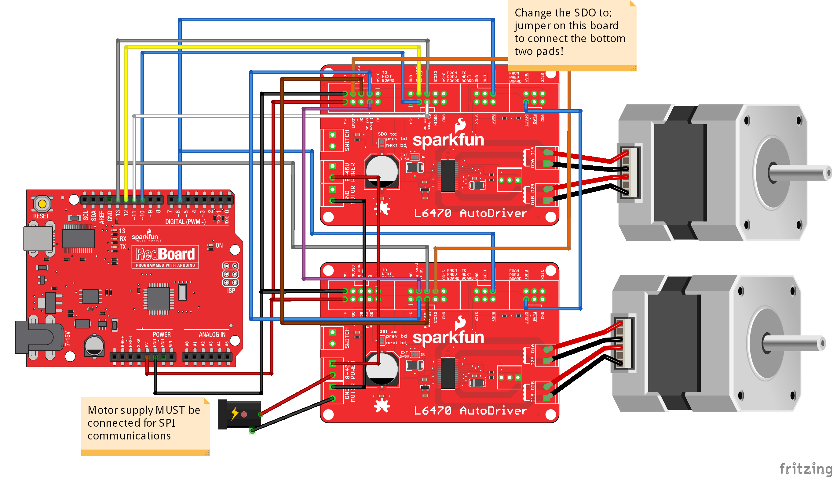
The two drivers are wired in daisy chain fashion according to the tutorial on the Sparkfun website.
There are 3 problems I have run into.
1. I set the configuration to use an external 16MHz oscillator, but when I read back the configuration it is the default value.
2. The second driver board (#0) in the daisy chain is not functioning. The way it is wired there is only 1 chip select for both boards??? And there is line in the sketch for telling the library what pin to use for this. The example code I am working from uses 6 motors, and uses the same chip select for all of them.
3. I can tell the first board to move the motor and it does. The test code posted below is supposed to move the motor 100 steps forward and then 100 steps reverse. The motor moves, but the sequence appears random. I have not been able to discern a distinct pattern. It moves forward several times in a row (with a pause in between), then decides it will move reverse several times. As I stated, the pattern appears random.
The two motors are named DECmotor and RAmotor. DECmotor is the one that works. Note that the farthest from the t4.0 in the daisy chain is #0, and #1 is the closest. DECmotor is #1.
Any ideas?
I have 2 Sparkfun L6470 Autodrivers connected to SPI port #2 on the t4.0 and have been trying to use the SparkFunAutoDriver.h library. I also have a GPS disciplined oscillator to provide a precise 16MHz for the Autodrivers.
The two drivers are wired in daisy chain fashion according to the tutorial on the Sparkfun website.
There are 3 problems I have run into.
1. I set the configuration to use an external 16MHz oscillator, but when I read back the configuration it is the default value.
2. The second driver board (#0) in the daisy chain is not functioning. The way it is wired there is only 1 chip select for both boards??? And there is line in the sketch for telling the library what pin to use for this. The example code I am working from uses 6 motors, and uses the same chip select for all of them.
3. I can tell the first board to move the motor and it does. The test code posted below is supposed to move the motor 100 steps forward and then 100 steps reverse. The motor moves, but the sequence appears random. I have not been able to discern a distinct pattern. It moves forward several times in a row (with a pause in between), then decides it will move reverse several times. As I stated, the pattern appears random.
The two motors are named DECmotor and RAmotor. DECmotor is the one that works. Note that the farthest from the t4.0 in the daisy chain is #0, and #1 is the closest. DECmotor is #1.
Any ideas?
Code:
#include <SparkFunAutoDriver.h>
#include <SparkFundSPINConstants.h>

#include <SPI.h>

// Create our AutoDriver instances. The parameters are the position in the chain of
//  boards (with board 0 being located at the end of the chain, farthest from the
//  controlling processor), CS pin, and reset pin.
#define motorCS 36
#define motorReset 31
#define motorBusy 32
#define NUM_BOARDS 2

// Numbering starts from the board farthest from the
//  controller and counts up from 0. Thus, board "4" is the
//  board which is plugged directly into the controller
//  and board "0" is the farthest away.
AutoDriver RAmotor(0, motorCS, motorReset);
AutoDriver DECmotor(1, motorCS, motorReset);

#define SPISPEED 2500000

void setup() {
  // put your setup code here, to run once:
 Serial.begin(9600);
  Serial.println("Hello world");
  // Start by setting up the SPI port and pins. The
  //  Autodriver library does not do this for you!
    pinMode(motorCS, OUTPUT);
    digitalWrite(motorCS, HIGH); // tied low is also OK.
    pinMode(motorBusy, INPUT);
    pinMode(motorReset, OUTPUT);
    digitalWrite(motorReset, LOW);
    delay(100); // LOW at least 4 clock cycles of onboard clock. 100 microseconds is enough
    digitalWrite(motorReset, HIGH); // now reset to default values

    delay(500);
    SPI2.begin(); //start the spi-bus


    // Configure the boards to the settings we wish to use
  //  for them. See below for more information about the
  //  settings applied.
  configureBoards();
}

// For ease of reading, we're just going to configure all the boards
//  to the same settings. It's working okay for me.
void configureBoards()
{

  Serial.println("Configuring motors...");

    // Before we do anything, we need to tell each board which SPI
    //  port we're using. Most of the time, there's only the one,
    //  but it's possible for some larger Arduino boards to have more
    //  than one, so don't take it for granted.
    DECmotor.SPIPortConnect(&SPI2);
     RAmotor.SPIPortConnect(&SPI2);
    // Set the Overcurrent Threshold to 6A. The OC detect circuit
    //  is quite sensitive; even if the current is only momentarily
    //  exceeded during acceleration or deceleration, the driver
    //  will shutdown. This is a per channel value; it's useful to
    //  consider worst case, which is startup. These motors have a
    //  1.8 ohm static winding resistance; at 12V, the current will
    //  exceed this limit, so we need to use the KVAL settings (see
    //  below) to trim that value back to a safe level.
    DECmotor.setOCThreshold(OC_6000mA);
    RAmotor.setOCThreshold(OC_6000mA);

    // KVAL is a modifier that sets the effective voltage applied
    //  to the motor. KVAL/255 * Vsupply = effective motor voltage.
    //  This lets us hammer the motor harder during some phases
    //  than others, and to use a higher voltage to achieve better
    //  torqure performance even if a motor isn't rated for such a
    //  high current. This system has 3V motors and a 12V supply.
    DECmotor.setRunKVAL(192);  // 128/255 * 12V = 6V
    DECmotor.setAccKVAL(192);  // 192/255 * 12V = 9V
    DECmotor.setDecKVAL(192);
    DECmotor.setHoldKVAL(128);  // 32/255 * 12V = 1.5V
    RAmotor.setRunKVAL(192);  // 128/255 * 12V = 6V
    RAmotor.setAccKVAL(192);  // 192/255 * 12V = 9V
    RAmotor.setDecKVAL(192);
    RAmotor.setHoldKVAL(128);  // 32/255 * 12V = 1.5V

    // When a move command is issued, max speed is the speed the
    //  motor tops out at while completing the move, in steps/s
    DECmotor.setMaxSpeed(30);
    RAmotor.setMaxSpeed(30);
    DECmotor.setMinSpeed(0.0);
    RAmotor.setMinSpeed(0.0);
    DECmotor.setLoSpdOpt(1);
    RAmotor.setLoSpdOpt(1);

    // Acceleration and deceleration in steps/s/s. Increasing this
    //  value makes the motor reach its full speed more quickly,
    //  at the cost of possibly causing it to slip and miss steps.
    DECmotor.setAcc(10);
    DECmotor.setDec(10);
    DECmotor.setSwitchMode(SW_HARD_STOP);
    DECmotor.setOscMode( EXT_16MHZ_XTAL_DRIVE );
    RAmotor.setAcc(1);
    RAmotor.setDec(1);
    RAmotor.setSwitchMode(SW_HARD_STOP);
    RAmotor.setOscMode( EXT_16MHZ_XTAL_DRIVE );

    DECmotor.configStepMode(STEP_FS_128);
    RAmotor.configStepMode(STEP_FS_128);
     RAmotor.getParam(CONFIG);
  Serial.print(CONFIG,HEX);Serial.print(" ");
  DECmotor.getParam(CONFIG);
  Serial.println(CONFIG,HEX);
  delay(2000);
}


void loop() {
  RAmotor.getParam(CONFIG);
  Serial.print(CONFIG,HEX);Serial.print(" ");
  DECmotor.getParam(CONFIG);
  Serial.println(CONFIG,HEX);
  Serial.println("Forward");
  delay(500);
  RAmotor.move(FWD, 100);
  DECmotor.move(FWD, 100);
  while (DECmotor.busyCheck()){}
  DECmotor.softStop();
  Serial.println("Reverse");
  delay(500);
  RAmotor.move(REV, 100);
  DECmotor.move(REV, 100);
  while (DECmotor.busyCheck()){}
   DECmotor.softStop();

}
 I guess I will have to order a couple new ones.