Neel
Member
Hello Everyone!
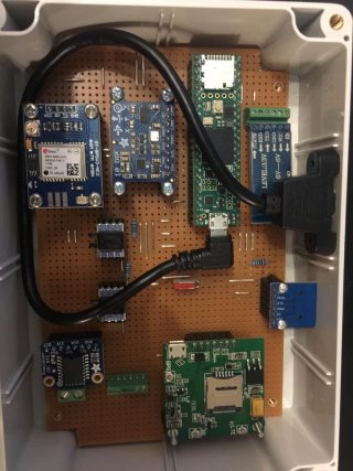
I have a question on the correct placement of the Adafruit 10-DOF IMU Breakout - L3GD20H + LSM303 + BMP180.
I have created a circuit board with a couple of Breakout boards attached and after reading the compass values, I realized it is way off. I tried calibrating it with the motion sensor calibration tool, namely from this website: https://www.pjrc.com/store/prop_shield.html. However, using the ahrs_mahony sketch from Paul, the values are still not correct. Do you guys reckon it could be due to the distance of the IMU breakout board to the neighboring board? If so, is there a rule of thumb on the minimum distance I can place this breakout board to the next magnetic field?


