MISO and MOSI ports for connecting LoRa to Teensy 3.2?

Status
Not open for further replies.
Hi.
I needed a board with 5V tolerant pins and a true analog output (DAC). So 3.2 seemed to fit the bill.

However, now I'm trying to connect a LoRa module to that board (Ra-01 containing SX1278), and the sample Rx code does not work: the LoRa fails to initialize.
I have connected the same LoRa module to an M0 board (Seeed), and it works fine.

When looking at the pinout for 3.2, I don't see any MISO and MOSI ports. I used pins 11 and 12 for those (as the only remaining SPI pins), but maybe that is incorrect.

Any tips or ideas would be appreciated ))

Nick.
 
Those are the correct pins, but in addition I assume you need an SPI clock pin, which typically is pin13.
Also it may also depend on your setup. For example if you are also using an Audio board, than you may need to move the clock to pin 14.
And to do so you need to do SPI.setSCK(14);

Beyond that all of the normal things like you need power to the chip plus common ground and a Chip select pin...
 
Thanks Kurt.
Lora's SCK is connected to pin13 of the 3.2.
The power measures at 3.33V at Lora's 3.3V pin.

I really hoped the MISO/MOSI pins were wrong )) I will have to keep digging.
 
When all else fail, try to swap MISO and MOSI, sometimes different devices give confusing names on IN and OUT but whose in and whose out...

Also again without seeing this, it helps to post pictures.

Might show things like you are using a breadboard with pins but the pins are not soldered to Teensy... Seen this several times now... Or maybe counting off by one... like you think your board is plugged into the last pins of a breadboard, but is actually starting at second one.. Seen it.... Done it...
And again what CS pin is used and is it configured properly...

So again it helps to see exactly the setup, code, ...
 
Teensy 3.2 shows the MOSI as data out and MISO as datain, refer to the Teensy 3.5 card for updated names. Kind of confusing. Do you use other SPI devices on the same bus as they could have tri-stating issues that would give you problems as well.
 
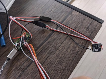
No other SPI devices. Tried to swap MISO and MOSI, no difference. Teensy's CS pin10 is connected to the NSS pin on the SX1278. No other SPI devices. No breadboard -- all soldered. Pic attached.
Could it be the CPU clock on the Teensy? When I get a compile error due to a typo in the code, I get this error message:

Arduino: 1.8.13 (Windows 10), TD: 1.53, Board: "Teensy 3.2 / 3.1, Serial, 96 MHz (overclock), Faster, US English". Is my 3.2 running at 96Mhz? I did not mess with the CPU clock. I think it's supposed to be at 72Mhz.

Has anyone got a 3.2 (as opposed to 3.6) working with Lora?
 
Here's the pic. It did not upload before b/c it was apparently too big...
IMG_20201003_165048-1.jpg
 
Sorry, I have never used this LoRA. I have played around with some RFM95 modules and a few others.
I have mainly played around with the RadioHead library.

Again it might help to see what the sample code is.. Also if there is any diagnostic sketches which you can see if the unit is talking to it or not.
 
I will try RFM95. For now, I tried the RadioHead library, using the Adafruit test code. I also tried Sandeep Mistry's LoRa library. The result is the same: lora won't initialize. But this module works well with a Seeed XAIO M0 board and the same code, just the pin assignments are different for NSS (aka CS) and RST. For now it looks like 3.2 cannot be used with lora, but I will try RFM95W. If any of the newer Teensies had a DAC, I'd try that one in a jiffy... But if I need to add hardware (even a DAC), I might as well just add an integrated M0/Lora board.
 
You have Teensy pins 11 and 12 wired incorrectly. They should be the other way round. MISO on the Ra-01 should go to MISO (pin 12) on the Teensy.

Pete
 
True. I originally had MISO on Ra going to pin12. Then I swapped them and took the pic after that. But neither config worked. The JR cables are ordered black-red-white. The red and white are criss-crossed going into the Teensy in the pic (white is in the middle), but it wasn't the case originally. Thanks for noticing.
 
Yes - as Pete mentioned you had it right the first time. But did not see picture earlier when I suggested that sometimes the devices are not clear on their labeling....

The other thing I should mention is when I was playing with the RFM95 and put on on one of my own experimental boards for communicating from my well house to the house, I put on it's own 3.3v VR to not use the the VR built into the Teensy. Don't remember if I needed to do this, or because I just wanted to make sure the 3.3v had enough current for the radio.

I know my first experiments were using the Adafruit breaktout boards, which also had their own 3.3v VR, so...
 
Not sure why?

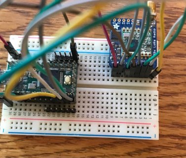
I pulled out an Adafruit RFM95 breakout board and a T3.2 and used Radiohead RFM95_Client example sketch. I wired it using pin 10 for CS and pin 2 for INT (default for library).

And ran it... The initialization appeared to work OK...
Code:
Sending to rf95_server
No reply, is rf95_server running?
Sending to rf95_server
No reply, is rf95_server running?
Sending to rf95_server
No reply, is rf95_server running?
Sending to rf95_server
No reply, is rf95_server running?
Sending to rf95_server
No reply, is rf95_server running?
Sending to rf95_server
No reply, is rf95_server running?
Sending to rf95_server
No reply, is rf95_server running?
Sending to rf95_server
I did not setup anything for server...

IMG_1238.jpg
 
Whaaaat??? I'm gonna try to reproduce it. What is the significance of your INT pin? Is it G0/IRQ or is it RST? I had neither one connected on the M0 and it worked fine, but maybe I need to have both RST and IRQ connected on T3.2...
 
Ok. Got it to initialize, but packages are not being received. ))

On the initialization issue: the only difference with your pic (Kurt) was that you had the pins RST and DIO0/INT connected and I didn't. So I figured I'd connect those. Made a separate cable for them so that I can disconnect them. When those two pins are connected, Lora initializes ok. When disconnected, I get the same error as before. The main culprit is the INT pin, as I had RST connected before and still no luck. On a Seeed M0, the same setup works without the RST & INT pins connected. But that is a minor issue. I am fine connecting them to the 3.2 to get it to work.

Now, the LoRa library was working with two M0's this morning, but then I connected the 3.2, got it to initialize, and now the receiving module is not seeing packets even when connected back to the M0, lol. It may be a library issue of course, as there are long threads here re RadioHead receiver probs. Will have to see I guess....

But interesting that some boards don't require RST and INT to be connected while others do. Would have saved me a bunch of time if connected all pins right away.
 
Last edited:
Status
Not open for further replies.
Back
Top