SPI1 Maximum Speed?

Status
Not open for further replies.

Swap_File

Member
Is there a maximum speed for SPI1 on the teensy 4.1? I can easily push SPI to 32mhz, but SPI1 seems to choke between 26 and 27mhz.

Code:
#include <SPI.h>

#define PAYLOAD 4096
uint16_t dac[PAYLOAD];

void setup()
{
  pinMode(2, OUTPUT);
  SPI1.begin();
  
  //WORKS
  SPI1.beginTransaction(SPISettings(26000000, LSBFIRST, SPI_MODE0));
  
  //DOESNT WORK
  //SPI1.beginTransaction(SPISettings(27000000, LSBFIRST, SPI_MODE0));

  for (int i = 0; i < PAYLOAD; i++)  {
    dac[i] = i % 0xFFFF;
  }
}


void loop()
{
 
  digitalWriteFast(2, LOW);
  for (int i = 0; i < PAYLOAD; i++)  {

    digitalWriteFast(2, LOW);  
    SPI1.transfer16(dac[i]);
    digitalWriteFast(2, HIGH); 
  }
  digitalWriteFast(2, HIGH);
  delay(10);
}
 
Hard to say. There should be more or less be no difference between SPI and SPI1 and SPI2 on the Teensy 4 boards.

That is they run off of the same clock settings in the CCM section. They setup the pins the same way...
under the covers SPI (uses LPSPI4 on imxrt) and SPI uses LPSPI3.

Again hoard to say when you say works and choke what that implies.

But it works fine on my machine using your programs.
Note: sometimes there are jumps in speed. As it tries to give you an SPI speed that does not exceed the speed you passed in. So would have to compute what the actual computed speed is for both of these.

But again same code runs on SPI and SPI1 so should not differ.
 
I connected my oscilloscope to look at the waveforms. They both look fine to me.

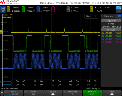
Here's what I see with the first line for 26 MHz

file.png

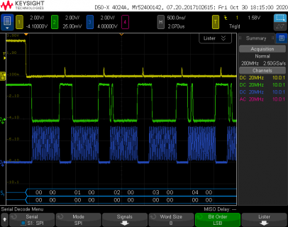
And here is the result if I comment out the 26 MHz line and put in the 27 MHz config.

file2.png
 
As you can see by the gaps between the burst of clock pulses on the blue trace, stopping to toggle pin 2 really slows the whole transfer.

If your device can work without CS changing every 16 bits, everything can run much faster with just SPI1.transfer(dac, NULL, sizeof(dac));
 
I ran one more quick test to check the actual SPI clock frequency.

The meaning of SPISettings is a maximum frequency. The SPI port gives you the highest frequency it can without exceeding that threshold. Because the hardware divides a reference clock, the actual frequencies is can produce are discrete steps.

SPISettings(26000000, LSBFIRST, SPI_MODE0) is actually generating 24 MHz.

SPISettings(27000000, LSBFIRST, SPI_MODE0) is actually generating 26.6 MHz.

About your original question, my best (blind) guess is you may be experiencing pretty bad signal quality problems with wiring between Teensy 4.1 and your DAC chip. Maybe it's just barely working at 24 MHz and then 26.6 MHz pushes things just a little too far?

Teensy definitely is transmitting good waveforms, as you can see, so I'd recommend you focus on improving your wiring.

Here's a few tips you can try to improve signal quality.

1: Use shorter wires

2: Use a ground wire together with each signal wire. Keep them as close as possible, ideally tightly twisted together. Of course the ground wire needs to connect to GND on both ends with as little extra wire as reasonably possible.

3: Add a low value resistor between the Teensy pin and wire. The ideal resistor value to use depends on the type of wire and how close you keep the ground wire to the signal wire. But the good news is even a resistor that's off quite a bit from ideal still helps quite a lot. Values between 22 to 150 ohms are the likely range. Probably best to start with 33 or 47 ohms as a first guess.
 
Thanks for your quick replies. To clarify, when I said choke I meant that nothing would be output on SPI1 (CLK or DATA), either on my logic analyzer or when I probed the points with analog probes. Here is a picture of my setup working with the analyzer plugged in.
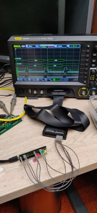
IMG_20201031_094043.jpg

I tried running my tests again this morning after reading your emails, and everything worked, I really don't know what could have changed. Is there any way I could have broken something that could have persisted across code uploads (but fixed itself when I power cycled over night)? I was messing with writing directly to registers.

The code I uploaded yesterday was a minimal test program, but ultimately I want to write directly to the DACs as fast as possible (while still being able to toggle a sync). See below for a bigger snippet of code, I basically just cannibalized the transfer16 function. I'm also considering using SPI2 to control a 3rd DAC, for full X Y and Z control of a vector monitor. Or I might piggyback Z onto the X or Y DAC, because most of the time I need to delay for a bit when turning the beam off or on anyway. (and delay means leaving the dac values unchanged, since the stream of data going to the dac is effectively drawing the scene)
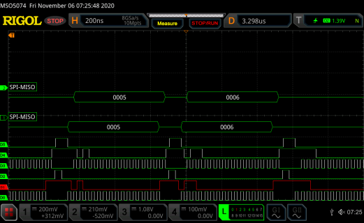
RigolDS12.png

Code:
#include "SPI.h"

#define SPI_TCR 0x60
#define SPI_TDR 0x64
#define SPI_RSR 0x70
#define SPI_RDR 0x74
#define SPI0ADDR(x) (*(volatile unsigned long *)(0x403A0000 + x))
#define SPI1ADDR(x) (*(volatile unsigned long *)(0x4039C000 + x))

#define PAYLOAD 4096
uint16_t dac[PAYLOAD];

#define DACX_SYNC_PIN 2
#define DACY_SYNC_PIN 3

void setup()
{
  // set the slaveSelectPin as an output:
  pinMode(DACX_SYNC_PIN, OUTPUT);
  pinMode(DACY_SYNC_PIN, OUTPUT);
  // initialize SPI:
  SPI.begin();
  SPI.beginTransaction(SPISettings(32000000, LSBFIRST, SPI_MODE0));
  SPI1.begin();
  SPI1.beginTransaction(SPISettings(32000000, LSBFIRST, SPI_MODE0));
  for (int i = 0; i < PAYLOAD; i++)
  {
    dac[i] = i % 0xFFFF;
  }

  SPI0ADDR(SPI_TCR) = (SPI0ADDR(SPI_TCR) & 0xfffff000) | LPSPI_TCR_FRAMESZ(15); // turn on 16 bit mode
  SPI1ADDR(SPI_TCR) = (SPI1ADDR(SPI_TCR) & 0xfffff000) | LPSPI_TCR_FRAMESZ(15); // turn on 16 bit mode

}

void loop()
{
  digitalWriteFast(DACX_SYNC_PIN, LOW);
  digitalWriteFast(DACY_SYNC_PIN, LOW);
  int temp;
  for (int i = 0; i < PAYLOAD; i++)
  {
    SPI0ADDR(SPI_TDR) = dac[i]; // output x
    digitalWriteFast(DACX_SYNC_PIN, LOW);  // this will go low before x transmission starts
    SPI1ADDR(SPI_TDR) = dac[i]; // output y
    digitalWriteFast(DACY_SYNC_PIN, LOW);   // this will go low before y transmission starts
    delayNanoseconds(510);
    temp = SPI0ADDR(SPI_RDR);
    temp = SPI1ADDR(SPI_RDR);
    digitalWriteFast(DACX_SYNC_PIN, HIGH);
    digitalWriteFast(DACY_SYNC_PIN, HIGH);
  }
  digitalWriteFast(DACX_SYNC_PIN, HIGH);
  digitalWriteFast(DACY_SYNC_PIN, HIGH);

  delay(10);
}

I'm basically aiming to make an improved VST board: https://github.com/osresearch/vst, the old teensy 3 did not have enough memory to buffer a full frame of data, so it had to render the scene realtime, filling a spi buffer that was DMA'ed out in the background to the Dacs, but this would often cause sparkling or bright spots as the rendering speed changed. From what I can tell, the teensy 4 should have no problem buffering an entire scene in advance and spamming it out at a fixed rate, no DMA needed.

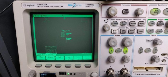
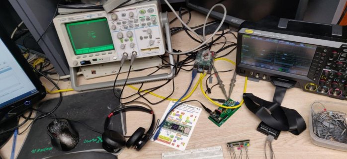
Here is a teensy 3 running the old VST program:
IMG_20201031_102331.jpg
IMG_20201031_102338.jpg
(XY works a lot better on the older scope)

Thanks again for your suggestions, I should have waited a day to post my question.
 
Last edited:
Glad it is working better now.

Actually not a bad question to ask, especially given that SPI1 and the like on T3.x are different than SPI object under the hood. Like which clock drives them, and size of FIFO (4 for SPI 1 for SPI2...)...

But in the case of IMXRT they are the same.

Sounds like fun!
 
BTW expecting stuff to work above about 25MHz on a breadboard is really pushing it - I've seen high speed stuff on
a breadboard work upto 40MHz (sometimes), and fail completely at 80MHz. Without a groundplane you have the
issue that the ground return currents are all over the place, hoping from wire to wire. The more ground network
you can distribute over the breadboard the more likely you are to have it work at high speed (ie emulate a
groundplane as best you can with lots of ground wiring in a grid).

When passing signals across distance always route ground return wires alongside signals and keep wiring direct
and neat (no big loops up in the air for instance)

I strongly recommend making your own hookup wires from 0.6mm diameter single-strand wire, so you can
cut each to the ideal length - the premade wires with dupont crimp pins are not very suitable for high speed
setups, as they cannot be laid flat and tidy.
 
Status
Not open for further replies.
Back
Top