Gamepad emulation using teensy 4.0

Status
Not open for further replies.
Hi guys.

Is it possible to emulate a gamepad using a teensy 4.0 or only a specific teensy model can emulate a gamepad?

I am looking into making xinput controller using the teensy 4.0, same as it has been done here with a different microcontroller

https://www.partsnotincluded.com/how-to-emulate-an-xbox-controller-with-arduino-xinput/

Thanks

It depends on the code, and what devices the code uses. There are a few things that might prevent it from working on a Teensy 4.0/4.1. Many of things are minor, and can be changed in the code:
  • The define for the Teensy 4.0/4.1 processor is different from the older Teensies. So if the code only explicitly checks for a Teensy LC, 3.2, 3.5, or 3.6, it might miss the Teensy 4.0 or 4.1. If it checks the higher level define (CORE_TEENSY), it may be fine.
  • Only the first serial port is in the same location in all of the Teensy LC, 3.x, or 4.x. If the code uses Serial2 or Serial3, then you would need to use different pins. Given it also runs on AVR processors like the Leonardo that only have one serial port, I suspect it may not be an issue.
  • If it uses a DAC (digital -> analog converter) to produce sounds, that will be a problem on the Teensy 4.0/4.1, which does not have a DAC. There are various ways to do sound on the Teensy 4.0/4.1, but it will involve re-coding the parts, and perhaps some trade-offs in terms of pin selection.
  • If it uses analog pins A10 and A11 (on the inside of the Teensy LC, 3.x), these pins aren't in that position in the Teensy 4.0/4.1 (and on the 4.0, A10/A11 are on solder pads underneath the Teensy).
  • If it uses the analog reference pin (AREF), the Teensy 4.0/4.1 doesn't have an AREF. If you are using AREF, but not setting it to an explicit value, you can generally use 3.3v as AREF.
  • The code appears to have its own boards.txt file to add options. You would need to add equivalent options for the Teensy 4.0/4.1.

Thank you for the reply.
I see. So it would be not that easy for novice like me

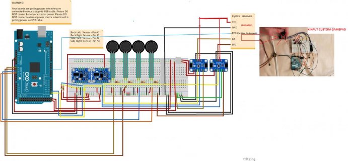
The reason why I am asking about the 4.0 is because it has two i2c channels, and I need that for the project I have been doing and shared here on the forum
 
I would like to share a method I was using when my system was running on the mega.
Maybe I can do the same with the teensy 4.0

I can actually connect the teensy 4.0 to the leonardo by replacing the joystick hooked on the leonardo.
I wish the code of the xinput controller would be updated for the teensy 4.0 of course.

Custom locomotion for xinput controller.jpg

code for the leonardo

Code:
/*
 *  Project     Arduino XInput Library
 *  @author     David Madison
 *  @link       github.com/dmadison/ArduinoXInput
 *  @license    MIT - Copyright (c) 2019 David Madison
 *
 * Permission is hereby granted, free of charge, to any person obtaining a copy
 * of this software and associated documentation files (the "Software"), to deal
 * in the Software without restriction, including without limitation the rights
 * to use, copy, modify, merge, publish, distribute, sublicense, and/or sell
 * copies of the Software, and to permit persons to whom the Software is
 * furnished to do so, subject to the following conditions:
 *
 * The above copyright notice and this permission notice shall be included in
 * all copies or substantial portions of the Software.
 *
 * THE SOFTWARE IS PROVIDED "AS IS", WITHOUT WARRANTY OF ANY KIND, EXPRESS OR
 * IMPLIED, INCLUDING BUT NOT LIMITED TO THE WARRANTIES OF MERCHANTABILITY,
 * FITNESS FOR A PARTICULAR PURPOSE AND NONINFRINGEMENT. IN NO EVENT SHALL THE
 * AUTHORS OR COPYRIGHT HOLDERS BE LIABLE FOR ANY CLAIM, DAMAGES OR OTHER
 * LIABILITY, WHETHER IN AN ACTION OF CONTRACT, TORT OR OTHERWISE, ARISING FROM,
 * OUT OF OR IN CONNECTION WITH THE SOFTWARE OR THE USE OR OTHER DEALINGS IN
 * THE SOFTWARE.
 *
 *  Example:      GamepadPins
 *  Description:  Uses all of the available pin inputs to build a 'complete'
 *                Xbox gamepad, with both analog joysticks, both triggers,
 *                and all of the main buttons.
 *
 *                * Joysticks should be your typical 10k dual potentiometers.
 *                * Triggers can be either analog (pots) or digital (buttons).
 *                  Set the 'TriggerButtons' variable to change between the two.
 *                * Buttons use the internal pull-ups and should be connected
 *                  directly to ground.
 *
 *                These pins are designed around the Leonardo's layout. You
 *                may need to change the pin numbers if you're using a
 *                different board type
 *
 */

#include <XInput.h>

// Setup
const boolean UseLeftJoystick   = true;  // set to true to enable left joystick
const boolean InvertLeftYAxis   = false;  // set to true to use inverted left joy Y

const boolean UseRightJoystick  = false;  // set to true to enable right joystick
const boolean InvertRightYAxis  = false;  // set to true to use inverted right joy Y

const boolean UseTriggerButtons = true;   // set to false if using analog triggers

const int ADC_Max = 1023;  // 10 bit

// Joystick Pins
const int Pin_LeftJoyX  = A0;
const int Pin_LeftJoyY  = A1;
const int Pin_RightJoyX = A2;
const int Pin_RightJoyY = A3;

// Trigger Pins
const int Pin_TriggerL = A4;
const int Pin_TriggerR = A5;

// Button Pins
const int Pin_ButtonA = 0;
const int Pin_ButtonB = 1;
const int Pin_ButtonX = 2;
const int Pin_ButtonY = 3;

const int Pin_ButtonLB = 4;
const int Pin_ButtonRB = 5;

const int Pin_ButtonBack  = 6;
const int Pin_ButtonStart = 7;

const int Pin_ButtonL3 = 8;
const int Pin_ButtonR3 = 9;

// Directional Pad Pins
const int Pin_DpadUp    = 10;
const int Pin_DpadDown  = 11;
const int Pin_DpadLeft  = 12;
const int Pin_DpadRight = 13;

void setup() {
  // If using buttons for the triggers, use internal pull-up resistors
  if (UseTriggerButtons == true) {
    pinMode(Pin_TriggerL, INPUT_PULLUP);
    pinMode(Pin_TriggerR, INPUT_PULLUP);
  }
  // If using potentiometers for the triggers, set range
  else {
    XInput.setTriggerRange(0, ADC_Max);
  }

  // Set buttons as inputs, using internal pull-up resistors
  pinMode(Pin_ButtonA, INPUT_PULLUP);
  pinMode(Pin_ButtonB, INPUT_PULLUP);
  pinMode(Pin_ButtonX, INPUT_PULLUP);
  pinMode(Pin_ButtonY, INPUT_PULLUP);

  pinMode(Pin_ButtonLB, INPUT_PULLUP);
  pinMode(Pin_ButtonRB, INPUT_PULLUP);

  pinMode(Pin_ButtonBack, INPUT_PULLUP);
  pinMode(Pin_ButtonStart, INPUT_PULLUP);

  pinMode(Pin_ButtonL3, INPUT_PULLUP);
  pinMode(Pin_ButtonR3, INPUT_PULLUP);

  pinMode(Pin_DpadUp, INPUT_PULLUP);
  pinMode(Pin_DpadDown, INPUT_PULLUP);
  pinMode(Pin_DpadLeft, INPUT_PULLUP);
  pinMode(Pin_DpadRight, INPUT_PULLUP);

  XInput.setJoystickRange(0, ADC_Max);  // Set joystick range to the ADC
  XInput.setAutoSend(false);  // Wait for all controls before sending

  XInput.begin();
}

void loop() {
  // Read pin values and store in variables
  // (Note the "!" to invert the state, because LOW = pressed)
  boolean buttonA = !digitalRead(Pin_ButtonA);
  boolean buttonB = !digitalRead(Pin_ButtonB);
  boolean buttonX = !digitalRead(Pin_ButtonX);
  boolean buttonY = !digitalRead(Pin_ButtonY);

  boolean buttonLB = !digitalRead(Pin_ButtonLB);
  boolean buttonRB = !digitalRead(Pin_ButtonRB);

  boolean buttonBack  = !digitalRead(Pin_ButtonBack);
  boolean buttonStart = !digitalRead(Pin_ButtonStart);

  boolean buttonL3 = !digitalRead(Pin_ButtonL3);
  boolean buttonR3 = !digitalRead(Pin_ButtonR3);

  boolean dpadUp    = !digitalRead(Pin_DpadUp);
  boolean dpadDown  = !digitalRead(Pin_DpadDown);
  boolean dpadLeft  = !digitalRead(Pin_DpadLeft);
  boolean dpadRight = !digitalRead(Pin_DpadRight);

  // Set XInput buttons
  XInput.setButton(BUTTON_A, buttonA);
  XInput.setButton(BUTTON_B, buttonB);
  XInput.setButton(BUTTON_X, buttonX);
  XInput.setButton(BUTTON_Y, buttonY);

  XInput.setButton(BUTTON_LB, buttonLB);
  XInput.setButton(BUTTON_RB, buttonRB);

  XInput.setButton(BUTTON_BACK, buttonBack);
  XInput.setButton(BUTTON_START, buttonStart);

  XInput.setButton(BUTTON_L3, buttonL3);
  XInput.setButton(BUTTON_R3, buttonR3);

  // Set XInput DPAD values
  XInput.setDpad(dpadUp, dpadDown, dpadLeft, dpadRight);

  // Set XInput trigger values
  if (UseTriggerButtons == true) {
    // Read trigger buttons
    boolean triggerLeft  = !digitalRead(Pin_TriggerL);
    boolean triggerRight = !digitalRead(Pin_TriggerR);
    
    // Set the triggers as if they were buttons
    XInput.setButton(TRIGGER_LEFT, triggerLeft);
    XInput.setButton(TRIGGER_RIGHT, triggerRight);
  }
  else {
    // Read trigger potentiometer values
    int triggerLeft  = analogRead(Pin_TriggerL);
    int triggerRight = analogRead(Pin_TriggerR);

    // Set the trigger values as analog
    XInput.setTrigger(TRIGGER_LEFT, triggerLeft);
    XInput.setTrigger(TRIGGER_RIGHT, triggerRight);
  }

  // Set left joystick
  if (UseLeftJoystick == true) {
    int leftJoyX = analogRead(Pin_LeftJoyX);
    int leftJoyY = analogRead(Pin_LeftJoyY);

    // White lie here... most generic joysticks are typically
    // inverted by default. If the "Invert" variable is false
    // then we need to do this transformation.
    if (InvertLeftYAxis == false) {
      leftJoyY = ADC_Max - leftJoyY;
    }

    XInput.setJoystick(JOY_LEFT, leftJoyX, leftJoyY);
  }

  // Set right joystick
  if (UseRightJoystick == true) {
    int rightJoyX = analogRead(Pin_RightJoyX);
    int rightJoyY = analogRead(Pin_RightJoyY);

    if (InvertRightYAxis == false) {
      rightJoyY = ADC_Max - rightJoyY;
    }

    XInput.setJoystick(JOY_RIGHT, rightJoyX, rightJoyY);
  }

  // Send control data to the computer
  XInput.send();
}


My old Code for the mega

Code:
//#include <VarSpeedServo.h>
#include <Adafruit_Sensor.h>
#include <Adafruit_BNO055.h>
#include <utility/imumaths.h>
#include <Adafruit_DS3502.h>

#define SensorV 15
#define angle1 20
#define angle2 87

#define Button 4

#define Sensor_BL A0
#define Sensor_BR A1
#define Sensor_SL A2
#define Sensor_SR A3

//VarSpeedServo servo1;
//VarSpeedServo servo2;

Adafruit_DS3502 ds3502_1 = Adafruit_DS3502();
Adafruit_DS3502 ds3502_2 = Adafruit_DS3502();
Adafruit_BNO055 bno1 = Adafruit_BNO055(-1, 0x28);
Adafruit_BNO055 bno2 = Adafruit_BNO055(-1, 0x29);


int speed = 0;
int angle = 0;

int y1_axis = 0, y2_axis = 0;
int y1_last = 0, y2_last = 0;
int y1_thres = 0, y2_thres = 0;
int sensorBL;
int sensorBR;
int sensorSL;
int sensorSR;

int prev_y1_axis = 0;
int y1_hold = 0;
unsigned long timer;
int start = 0;
byte step = 0;
String steps ,  laststep;
int freq;
int runC;
int press1 = 0 , press2 = 0;

void setup() {
  Serial.begin(115200);
  pinMode(Button , OUTPUT);

  if (!bno1.begin())
  {
    Serial.print("Ooops, no BNO055 1 detected ... Check your wiring or I2C ADDR!");
    while (1);
  }

  delay(1000);

  if (!bno2.begin())
  {
    Serial.print("Ooops, no BNO055 1 detected ... Check your wiring or I2C ADDR!");
    while (1);
  }
  delay(1000);
  bno1.setExtCrystalUse(true);
  bno2.setExtCrystalUse(true);
  delay(100);

  if (!ds3502_1.begin(0x2A)) {
    Serial.println("Couldn't find digital potentiometer 1");
    while (1);
  }

  if (!ds3502_2.begin(0x2B)) {
    Serial.println("Couldn't find digital potentiometer 2");
    while (1);
  }

  Serial.println("Found DS3502 chip");

  /*servo1.attach(2);
    servo1.write(90);
    servo2.attach(3);
    servo2.write(90);*/

  unsigned long timer;
  Serial.println("Calibration...");
  while (millis() - timer < 10000) {
    imu::Vector<3> euler1 = bno1.getVector(Adafruit_BNO055::VECTOR_EULER);
    imu::Vector<3> euler2 = bno2.getVector(Adafruit_BNO055::VECTOR_EULER);

    y1_thres = euler1.z();
    y2_thres = euler2.z();
    Serial.print(".");
    delay(100);
  }
  Serial.println("\nDone");
  Serial.println(String(y1_thres) + " " + String(y2_thres));
  delay(3000);
}

void loop() {
  imu::Vector<3> euler1 = bno1.getVector(Adafruit_BNO055::VECTOR_EULER);
  imu::Vector<3> euler2 = bno2.getVector(Adafruit_BNO055::VECTOR_EULER);

  y1_axis = euler1.z();
  y2_axis = euler2.z();

  sensorBL = analogRead(Sensor_BL);
  sensorBR = analogRead(Sensor_BR);

  sensorSL = analogRead(Sensor_SL);
  sensorSR = analogRead(Sensor_SR);

  if (sensorSL > 10) {
    speed = map( sensorSL , 0 , 1023 , 0 , 255);
    if (sensorSL < 700) {
      //servo2.write(70, speed);
      ds3502_1.setWiperDefault(90);                //X-axis value here
      press1 = 1;
    }
    else {
      //servo2.write(3 , speed);
      ds3502_1.setWiperDefault(127);                //X-axis value here
      press1 = 1;
    }
  }
  else if (sensorSR > 10) {
    speed = map( sensorSR , 0 , 1023 , 0 , 255);

    if (sensorSR < 700) {
      //servo2.write(110, speed);
      ds3502_1.setWiperDefault(40);                //X-axis value here
      press1 = 1;
    }
    else {
      //servo2.write(177 , speed);
      ds3502_1.setWiperDefault(1);                //X-axis value here
      press1 = 1;
    }
  }
  else {
    //servo2.write(90 , 255);
    ds3502_1.setWiperDefault(64);                //X-axis value here
    press1 = 0;
  }


  //0 right  - 64 centr - 127 left

  if (sensorBL > 250) {
    speed = map( sensorBL , 0 , 1023 , 0 , 255);
    if (sensorBL < 500) { //less pressure 90+20=110
      //servo1.write(85 , speed);
      ds3502_2.setWiperDefault(90);                //Y-axis value here
      angle = 95;
      press2 = 1;
    }
    else if (sensorBL > 500) { //more pressre 90+90 = 180
      //servo1.write(105 , speed);
      ds3502_2.setWiperDefault(127);                //Y-axis value here
      angle = 105;
      press2 = 1;
    }
  }
  else if (sensorBR > 250) {
    speed = map( sensorBR , 0 , 1023 , 0 , 255);
    if (sensorBR < 500) {  //less pressure
      //servo1.write(85 , speed);
      ds3502_2.setWiperDefault(90);                //Y-axis value here
      angle = 95;
      press2 = 1;
    }
    else if  (sensorBR > 500) { //more pressre
      //servo1.write(105 , speed);
      ds3502_2.setWiperDefault(127);                //Y-axis value here
      angle = 105;
      press2 = 1;
    }
  }
  else if ((start == 0 || millis() - timer > 800) && y1_axis > y1_thres - SensorV && y1_axis < y1_thres + SensorV && y2_axis > y2_thres - SensorV && y2_axis < y2_thres + SensorV && sensorBL < 200 && sensorBR < 200) //flat dead end no servo movement - center position -  can we separate on different lines the pressure sensor and accell so that I can set the dead end value separately for the press sens and acc ?
  {
    if (angle == 70 && runC > 0) {
      angle = 78;
      //servo1.write( 78 , 20);
      ds3502_2.setWiperDefault(50);                //walk   -    Y-axis value here
      runC--;
      press2 = 1;
    }
    else {
      //servo1.write( 87 , 15);
      ds3502_2.setWiperDefault(64);                //stopped   -    Y-axis value here
      start = 1;
      angle = 87;
      press2 = 0;
    }
    //Serial.println("Servo goes to zero");
    step = 0;
    steps = "0";
  }
  else if ((y1_axis < y1_thres - SensorV) && (step == 0 || step == 2))
  {
    step = 1;
    steps = "1";
  }
  else if ((y2_axis < y2_thres - SensorV) && (step == 0 || step == 1))
  {
    step = 2;
    steps = "2";
  }

  if (!steps.equals(laststep)) {
    if ((step == 1 || step == 2)  &&  millis() - timer < 400) {
      if (freq > 1) {
        //servo1.write(70 , 20);
        ds3502_2.setWiperDefault(1);                //run  -   Y-axis value here
        angle = 70;
        press2 = 1;
      }
      else {
        //servo1.write(78 , 20);
        ds3502_2.setWiperDefault(50);                //walk   -    Y-axis value here
        angle = 78;
        press2 = 1;
      }
      freq++;
      runC = 1;
    }
    else if ((step == 1 || step == 2 &&  millis() - timer > 675)) {
      //servo1.write(78 , 20);
      ds3502_2.setWiperDefault(50);                //walk   -      Y-axis value here
      angle = 78;
      freq = 1;
      press2 = 1;
    }
    timer = millis();
  }

  if (press1 == 1 || press2 == 1)
    digitalWrite(Button , LOW);
  else
    digitalWrite(Button , HIGH);

  Serial.println("Button: " + String(digitalRead(Button)) + " Y1: " + String(y1_axis) + " Y2: " + String(y2_axis) + " S1: " + String(sensorBL) + " S2: " + String(sensorBR) + " Angle: " + String(angle));
  laststep = steps;
  delay(80);
}

and I also made the xinput controller wireless using a minirouter and virtualhere, same as i did for this psaim controller that I made wireless connected to the pc

[video]https://streamable.com/t4599[/video]
 
Status
Not open for further replies.
Back
Top