Some questions on Teensy4.1 board

Status
Not open for further replies.
Hi everything.

I'm trying to use Teensy4.1 board for my hobby project. I have a couple questions with the Teensy4.1 board.
1. teensy4.1.png
I'm not sure what are those signals pointed out as the red rectangle.(They're near to the SD card slot) I already checked Teensy4.1 schematic. Are they 3.3V, GND, On/Off, Prog, and VBAT?
I need to know what are they.
2. teensy4.1_1.png
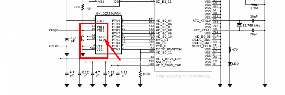
As you can see, MKL02Z32VFG4 have two pins(PTA0 and PTA1). What are they for? Is it necessary to use them to program MKL02Z32VFG4?

Thanks in advance.
Milovan
 
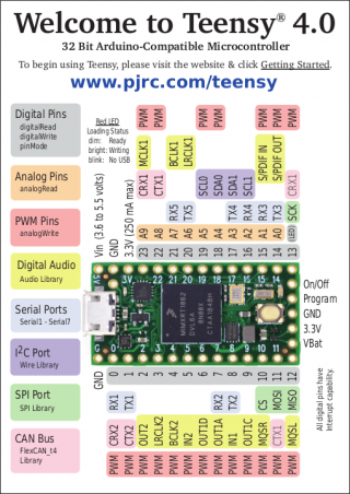
RE #1 :: For the function of all the center pins of the T_4.1 - refer to the same row ( alternate location on the end ) on the shorter T_4.0.

teensy40_pinout1.png

RE #2 :: Safe to assume anything connected to the MKL02Z32VFG4 is required to put the "Teensy" USB programmability into the Teensy from that PJRC Custom coded bootloader chip.
 
As you can see, MKL02Z32VFG4 have two pins(PTA0 and PTA1). What are they for?

Those are test points which PJRC uses to test the circuit board. You'll see the schematic has several more test points scattered across the power supply area. All of them are little pads on the bottom side which mate with pogo pins on a test fixture.


Is it necessary to use them to program MKL02Z32VFG4?

No, not necessary. That chip comes pre-programmed with the bootloader which allows the entire board to be programmed by USB, and gives features like the 15 second restore. You're not meant to use those pins. If you do anyway, odds are strong you'll end up erasing the bootloader, which effectively bricks the board. The bootloader code isn't published, so if you erase it there is no way to restore. Best to leave those test points alone. Likewise for many of the test points which access various power supply points like the PLL capacitor. Best to just leave it alone so you don't disturb the clock generation circuitry. They're only used while testing the PCB.
 
Those are test points which PJRC uses to test the circuit board. You'll see the schematic has several more test points scattered across the power supply area. All of them are little pads on the bottom side which mate with pogo pins on a test fixture.


No, not necessary. That chip comes pre-programmed with the bootloader which allows the entire board to be programmed by USB, and gives features like the 15 second restore. You're not meant to use those pins. If you do anyway, odds are strong you'll end up erasing the bootloader, which effectively bricks the board. The bootloader code isn't published, so if you erase it there is no way to restore. Best to leave those test points alone. Likewise for many of the test points which access various power supply points like the PLL capacitor. Best to just leave it alone so you don't disturb the clock generation circuitry. They're only used while testing the PCB.

Hi @Paul,

Thanks for your help. I have a question. Where does the board have the test points. I can't see any test point in the board or schematic. Where are the test points you mentioned?
Thanks in advance.

Milovan
 
Hi Paul,

I'm adding the Teensy4.1 schematic to use IMX1062 chip on my custom board. I'm having a hard time to understand how to burn the bootloader and firmware on IMX.
There are many explanation for boot configuration, but I want to do everything only via usb otg1 port like in the Teensy4.1 board. Is it possible? I duplicated the teensy circuit to the custom board as it is. I added a MKL02Z32VFG4 to the board like in the Teensy board.
Or should I add JTAG header to the board for flashing the firmware and bootloader?
Would you like to let me know the best solution for programming the firmware and burning the bootloader on my custom board? Where can I find the reference design for it?

Thanks in advance
Milovan.

This post also duplicated on thread: Questions-on-Teensy4-1-schematic
 
Have you purchased and used a Teensy 4.1 board?

Maybe I'm reading too much into your questions, but I'm getting the impression you have not actually used Teensy 4.1 at all. Is that right?
 
Status
Not open for further replies.
Back
Top