You are using an out of date browser. It may not display this or other websites correctly.
You should upgrade or use an alternative browser.
You should upgrade or use an alternative browser.
Multiplexer Wiring
- Thread starter toutant
- Start date
- Status
- Not open for further replies.
KD0RC
Well-known member
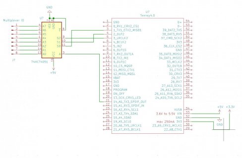
I don't think you want to use a 5 V device on a Teensy 4. I have had very good luck with the Sparkfun Mux boards with my Teensy 4.1. They will run on 3.3 V (Teensy safe) and have 16 analog or digital I/O lines not 8, but you can use 3 address lines and only use the first 8 I/O lines. These boards have room for .01 inch headers, so they are real easy to interface. In my project, I have two of these boards, giving me 32 I/O lines and only using 7 Teensy pins. The address lines and signal are in parallel across the MUXs and each MUX has its own Ena pin on the Teensy. The code below will work on one or two MUXs. You could remove the select MUX part and just have it work on one. I am using the MUXs for digital signals (buttons), but you could also use it for analog by changing the digitalRead() to analogRead(). You would also need to use an analog pin for Sig.
On my Teensy:
Pin 41 - EN, MUX 0
Pin 40 - S3, MUX 0 & 1 (addr line 3)
Pin 39 - S2, MUX 0 & 1 (addr line 2)
Pin 38 - S1, MUX 0 & 1 (addr line 1)
Pin 37 - S0, MUX 0 & 1 (addr line 0)
Pin 36 - Sig, MUX 0 & 1
Pin 35 - EN, MUX 1
https://www.sparkfun.com/products/9056
On my Teensy:
Pin 41 - EN, MUX 0
Pin 40 - S3, MUX 0 & 1 (addr line 3)
Pin 39 - S2, MUX 0 & 1 (addr line 2)
Pin 38 - S1, MUX 0 & 1 (addr line 1)
Pin 37 - S0, MUX 0 & 1 (addr line 0)
Pin 36 - Sig, MUX 0 & 1
Pin 35 - EN, MUX 1
Code:
void GetButton()
{
  GotBtn = false;

  // Select MUX board
  for(MUXidx=0; MUXidx<2; MUXidx++)
  {
    // Set Ena address on Teensy pins
    for(int i = 0; i<2; i++)
    {
      for(int j=0; j<2; j++)
      {
        digitalWrite(MUXEnaPin[j], HIGH);
      }
      digitalWrite(MUXEnaPin[MUXidx], bitRead(MUXidx,i));
    }

    delayMicroseconds(250);

    for(BTNidx=0; BTNidx<16; BTNidx++)
    {
      // Set Mux address on Teensy pins
      for(int k=0; k<4; k++)
      {
        digitalWrite(MUXPin[k], bitRead(BTNidx,k));
      }

      delayMicroseconds(250);

      if(digitalRead(MUXIOPin) == LOW)
      {
        Serial.print("Button "); Serial.print(MUXidx); Serial.print(" "); Serial.println(BTNidx);
        ResetScreenSaver();
        GotBtn = true;
        ButtonTime = millis();
        ProcessButtons();
        return;
      }
    }
  }
}
https://www.sparkfun.com/products/9056
It should be fine with 5V too. It is Analog switch MUX, so if you don't supply more than 3V3 on mux inputs, MCU should be fine. And TTL input levels are compatible with 3.3V CMOS output levels.
In fact, HTC series power supply range is between 4.5V to 5.5V. For 3.3V power supply the HC series will be better choice.
In fact, HTC series power supply range is between 4.5V to 5.5V. For 3.3V power supply the HC series will be better choice.
OK. That's what I thought I understood from Paul's comment on Teensy midi page.
For newer Teensy boards with 3.3V signals, 74HCT4051 chips are best. Power the 74HCT4051 from 5V. If 74HC4051 (without the "T") are used, they should be powered by 3.3V when used with a Teensy that has 3.3V signals, or by 5V when used with a Teensy having 5V signals.
Sounds like ideally the chip is powered from 5V, but I should bias all the pots at 0-3.3V.
Thanks!
- Status
- Not open for further replies.


